Disclaimer: Kimray does not manufacture or sell electric submersible pumps (ESPs). The following content is provided for educational purposes only and offers general information about ESPs in oil and gas production.
What is an electric submersible pump?
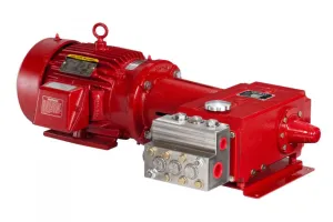
An electric submersible pump, abbreviated ESP, is a form of artificial lift that uses an electric motor to drive a multistage centrifugal pump to lift resources from the well.
In the article we'll explore the following topics:
- Why producers choose to use ESPs
- The components of an ESP system
- How it operates
- Advantages and disadvantages compared to other forms of artificial lift
Why oil and gas Producers Use electric submersible pumps
Producers use artificial lift systems in more than 90% of oil wells. Artificial lift is used to increase production fluids and are needed when reservoirs no longer have sufficient energy to naturally produce at economic rates, or to boost early production in new wells.
One effective and versatile method of artificial lift is the electric submersible pump.
Producers may choose to use an ESP system because they are quiet, safe and only require a small surface footprint.
They have a wide range of pump rate operation and can accommodate changes in fluid properties and flow rates over the life of the well. They’re also applicable in many corrosive environments.
ESP Systems Simplified
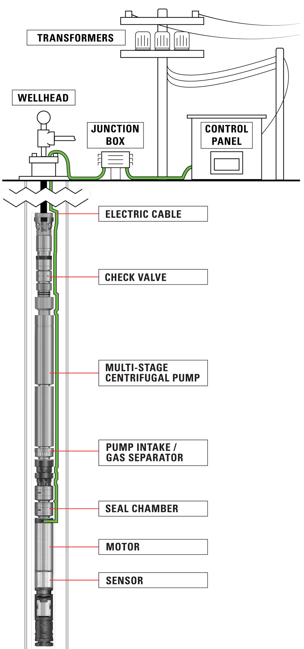
An ESP system consists of multiple stages of centrifugal pumps which are connected to a submersible electric motor. The motor is powered by heavy duty cables connected to surface controls.
The motor rotates the shaft which is connected to the pump. The spinning impellers draw in fluid through the pump intake, pressurizing it and lifting it to the surface.
An inverted discharge design is configured the same, with the exception that the pump stages are inverted to pump fluids into the well formation from the surface. This configuration is typically used for injection of water into disposal wells.
Let’s look at each component in more detail.
Components of an ESP System
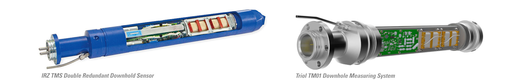
Sensor
To optimize performance, operators can install a downhole sensor that communicates real-time system data such as pump intake and discharge pressures, temperatures, and vibration.
Typically, producers monitor pumps through SCADA (supervisory control and data acquisition) systems. When it detects a pump reading that is outside the set point, a sensor alerts the operator in real time and changes can be made remotely or automatically by the surface controller.
Electric Motor
.png) The submersible pump is powered by an electric motor. The size of the motor and horsepower rating are determined by the number of stages needed to generate sufficient head pressure to lift the liquid to the surface.
The submersible pump is powered by an electric motor. The size of the motor and horsepower rating are determined by the number of stages needed to generate sufficient head pressure to lift the liquid to the surface.
Since the size of the motor varies, the overall length and diameter of ESP downhole equipment is determined by the motor size.
The motor temperature will increase as it operates but is cooled by the passing fluid being drawn into the pump. The motor is filled with synthetic oil for electrical protection and lubrication that also helps to evenly disperse the heat that is generated.
Seal-chamber
The seal-chamber isolates and protects the motor from damaging well fluids and equalizes the pressure in the wellbore with the oil pressure inside the motor.
It also absorbs the axial thrust produced by the pump and dissipates the heat that the thrust bearing generates.
PUMP: Shaft, Pump Intake and Stages (Impeller & Diffuser)
Shaft
The shaft connects the motor to the pump impellers through the seal-chamber. The shaft is designed to be as small in diameter as possible without compromising its strength; this allows greater volumes to pass through the pump intake.
There are different shaft materials for varying corrosive and erosive resistance, horsepower requirements and tensile strength.
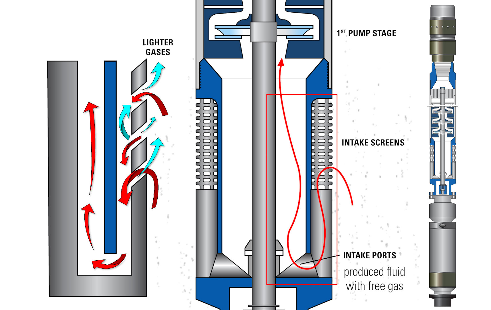
Pump Intake —Standard, Reverse-Flow, & Dynamic
The pump intake is where the well fluid enters the submersible pump and is directed into the impellers. Different types of intakes are used depending on fluid properties, particularly the gas-liquid ratio (GLR). Standard designs do not separate gas and are therefore used in wells that produce a very low gas-to-liquid ratio.
To separate gas in a well stream with relatively high GLR, producers use either a reverse-flow or rotary pump intake.
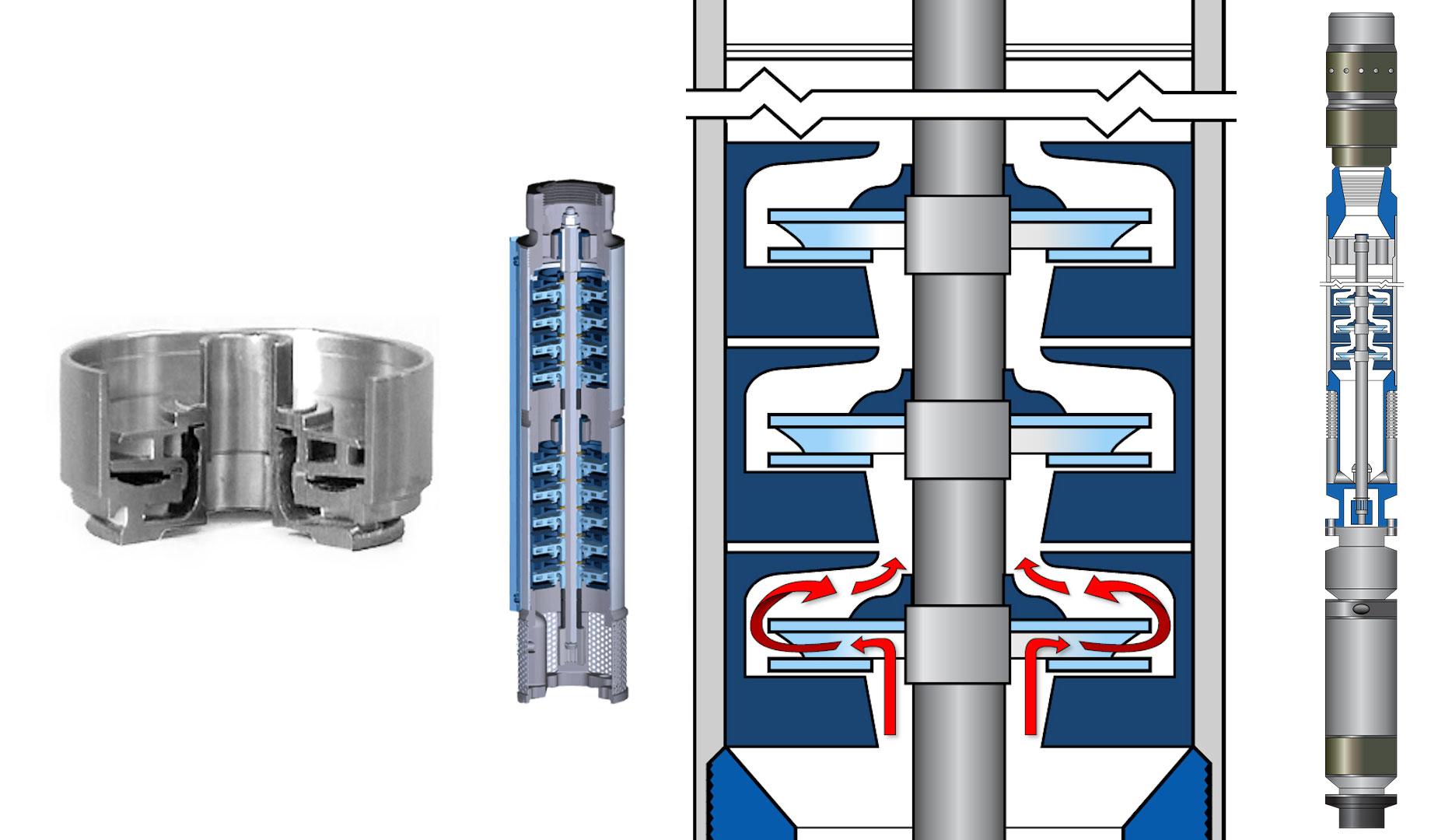
- In a reverse-flow pump intake the produced fluid with free gas flows up the outside of the reverse-flow intake screen then turns to enter through the perforations at the top of the screen. It then flows down to the intake ports and then back up to the first pump stage.
These reversals in direction allow for a natural separation of the lighter gases from the liquid. The separated gas travels up the casing annulus and exits the casing at the wellhead. Longer reversing paths can be utilized to increase the separation of the gas from the liquids.
- A rotary pump intake, also called a dynamic gas separator, uses force to help separate the gas. The rotary separator works similar to a centrifuge. It utilizes a rotating chamber, paddle wheel, or induced vortex to impart centrifugal force on the fluid.
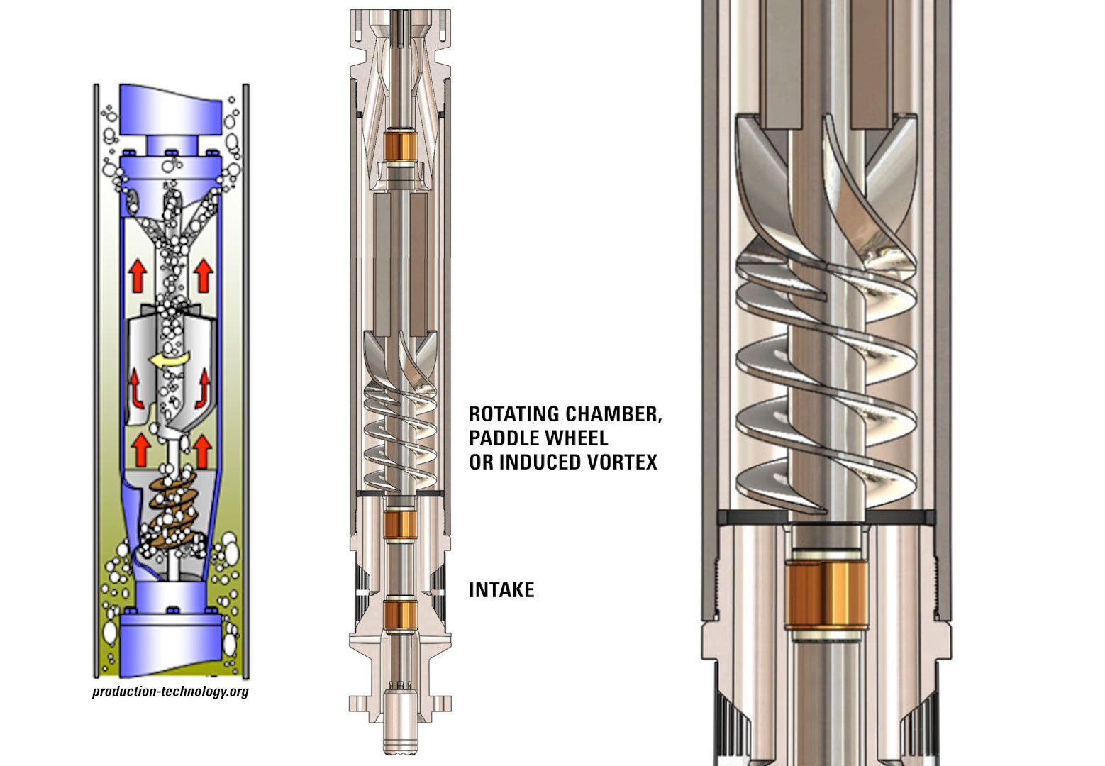
The rotor or induced vortex forces the heavier fluid to the outside & allows the free gas to migrate to the center of the chamber and exits through the discharge ports back into the well. Gas separator assemblies are often connected in tandem to improve the overall efficiency in high gas applications.
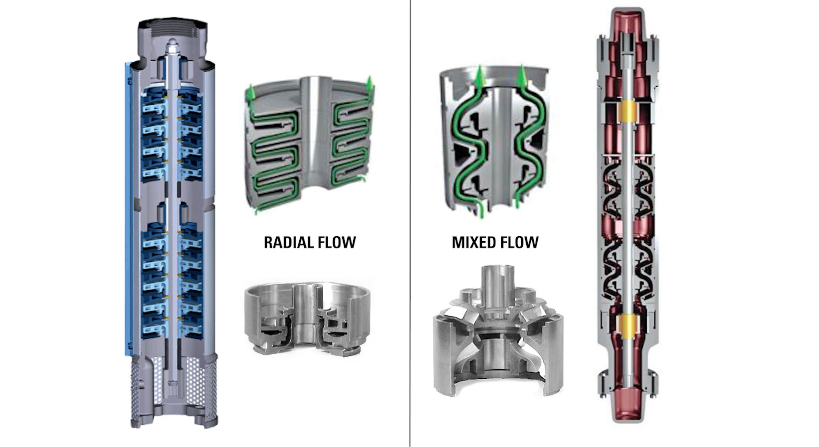
Centrifugal Pump (Impeller and Diffuser)—Stages
The stages of the centrifugal pump are what increase the pressure of the fluid. Each stage is made up of a rotating impeller and stationary diffuser. The stages can be stacked to incrementally increase the pressure until the desired flow rate is achieved.
The fluid travels through a rotating impeller which increases its kinetic energy, or velocity. It then enters the diffuser, converting the energy to potential energy which raises the discharge pressure. The fluid repeats the process in each stage of the pump.
This operation will continue until the fluid reaches the design discharge pressure. The increase in pressure is called the total developed head (TDH) of the pump.
The impellers are crucial to the operation of an ESP because they determine the flow rate. Radial flow impellers have vane angles close to 90 degrees and are usually for lower flow rates. Mixed flow impellers have vane angles close to 45 degrees and are for higher flow rates.
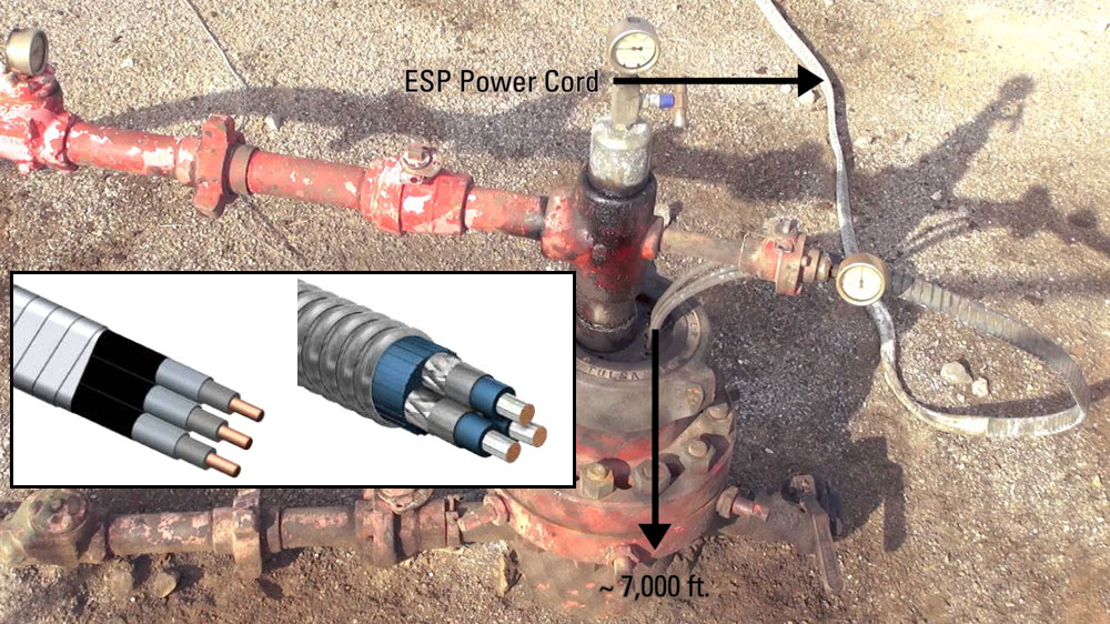
Power cable
The power cable delivers the required power to the ESP motor from the surface. It will be banded or strapped to the production tubing in intervals from below the wellhead to the motor to support its weight and keep mechanical wear from occurring.
It is a specially constructed power cable made for harsh environments with a durable outermost layer impervious to physical and electrical deterioration.
Check Valve
A check valve may be threaded into the tubing, a few joints above the pump. It is installed to keep the tubing above the pump full of liquid when the pump is not operating.
Surface components for the ESP include electrical supply, communication equipment and the ESP controller.
Controller
The ESP controller maintains the proper flow of electricity to the pump motor. Depending on the application, variable speed or soft-start controllers are used.
- A variable speed drive (VSD) can be either manual or automated. An automated VSD reads the downhole data recorded by the SCADA system and adjusts the motor speed to optimize production rates. The VSD allows the pump to be operated continuously or intermittently.
- A soft-start controller operates at only one speed. To prevent the motor from being under a heavy load at the start, it slowly brings the pump motor up to its designed operation speed and maintains that single speed.
Advantages of using an Electric Submersible Pump
- Adaptable to highly deviated or horizontal wells but must be set in straight section.
- Permit use of minimum space for subsurface controls and associated production facilities.
- ESPs are quiet, safe and require a smaller surface footprint compared to other lift systems, making them the best option in offshore and environmentally sensitive areas.
- High volume capabilities. ESPs can accommodate the dynamic evolution of fluid properties and flow rates during the life of the well.
- Provides for increased volumes and water cuts brought on by pressure maintenance and secondary recovery operations.
- Allows placing wells on production even while drilling and working over wells in the immediate vicinity.
- Applicable in a range of corrosive environments. The pumps can be manufactured from high-grade, corrosion-resistant materials for applications with high-GOR fluids, high temperatures and fluids containing corrosive acid gases.
Disadvantages of using an Electric Submersible Pump
- Will tolerate only minimal percentages of solids in production. Although special pumps with hardened materials exist, ESP run times can be severely compromised in fluids with a high percentage of sand and solids.
- Costly removal operations and lost production occur when correcting downhole failures.
- With lower than 400 BBLD volumes, power efficiency drops sharply; ESPs are not particularly adaptable to rates below 150 BBLD.
- Need relatively large (greater than 4½-in. outside diameter) casing size for the moderate- to high-production-rate equipment.
To learn more about other types of artificial lift, check out our videos on plunger lift or gas lift systems.