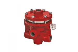
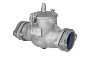
Looking for practical steps to take to achieve your ESG commitments? One source of natural gas emissions may be your back pressure regulator.
We’ll show you a simple change you can make to prevent your back pressure regulators from venting natural gas.
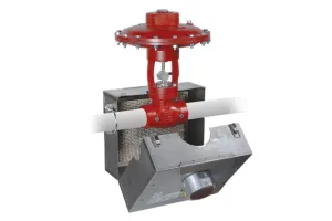
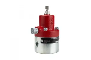
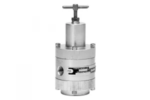
The 330 SGT BPOS was installed on our separator and commissioned 7/15/22. There were no issues to report during startup, and once in service, the valve functioned correctly.”
-Engineer, E&P in the Delaware Basin
Options for Zero-Emission Regulators
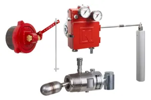
To eliminate emissions from your regulator, you have two options:
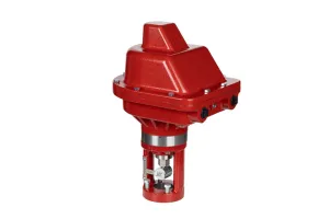
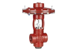
- Non-Venting Regulator
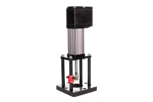
- Outside Supply Regulator, Operating with Liquid Nitrogen or Compressed Air
Either option can be purchased new, or you can easily convert an existing regulator to either operation with only a few extra parts.
* The outside supply regulator will fail open when you lose supply gas.
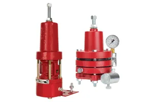
Non-Vent Regulators vs Outside Supply Regulators
Why choose one or the other? If your pressure differential—or the pressure drop across the valve (𝚫P)—is 10 PSI or less, we recommend converting to an outside source of supply air.
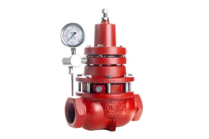
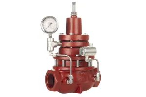
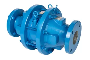
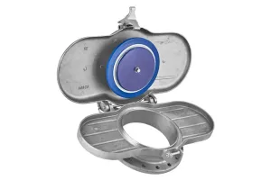
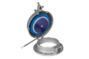
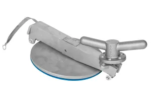
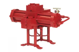
The back pressure regulator with outside supply (BPOS) can be used to eliminate emissions when you incorporate an air compressor into your operation for instrument supply.
Note that you can also use the BPOS to hold back pressure in wet gas applications to reduce the likelihood of malfunction due to heavy condensate. This was the primary use of this product’s predecessor, the liquid back pressure regulator.
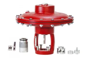
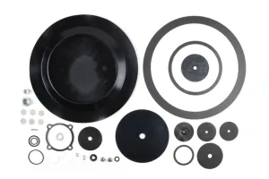
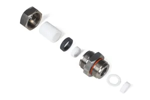
Conversion & Repair Kit
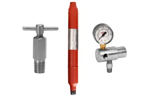
Tools & Parts Needed
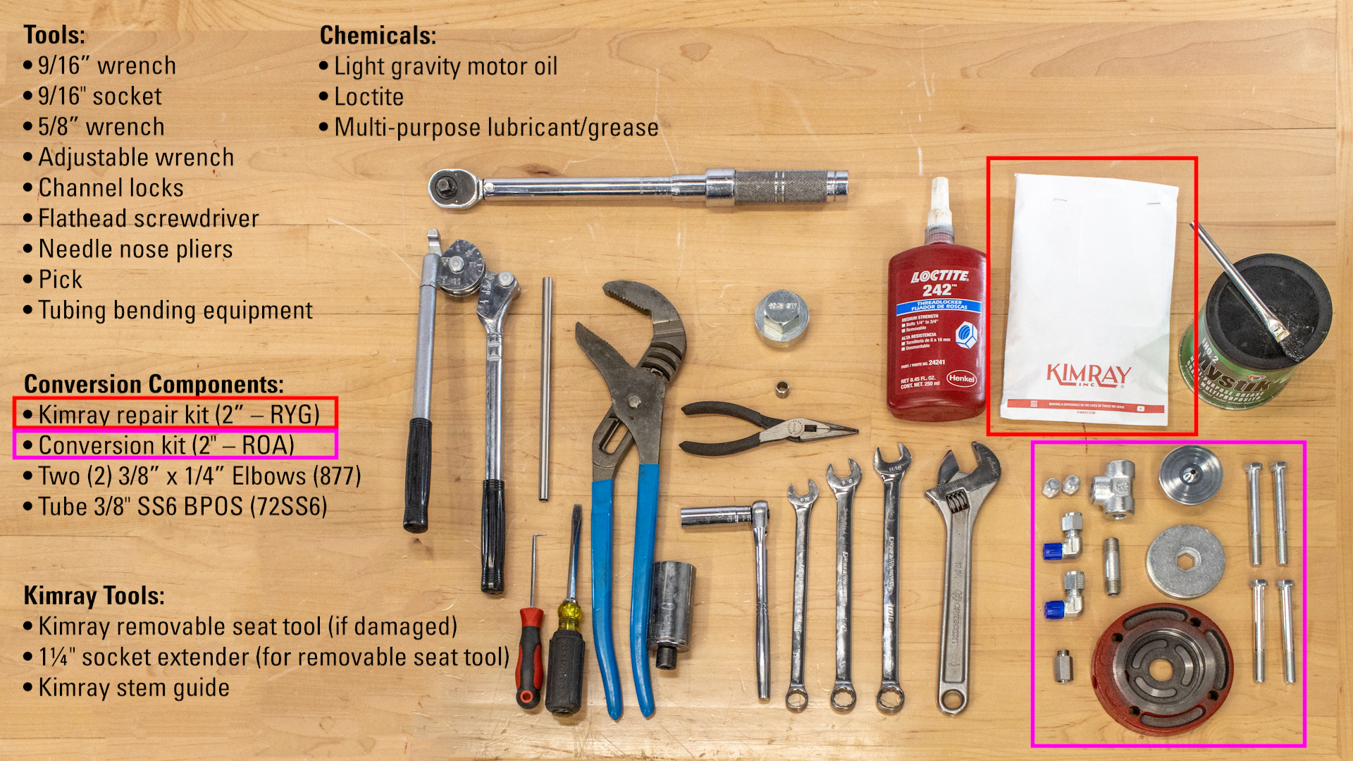
When you’re doing a conversion, we recommend also installing a repair kit. We’ll be showing both processes in this video. For a 2" Back Pressure Regulator conversion and repair, you will need the following tools and components:
- 9/16” Wrench & Socket
- 5/8” Wrench
- Channel Locks (x2 if not using a vise)
- Adjustable Wrench
- Multi-Purpose Lubricant/Grease
- Flathead Screwdriver (if needed to Separate Housing)
- 1¼" Socket Extender (if using Removable Seat Tool)
- Needle Nose Pliers (to remove Filter Screens)
- Any Kind of Light Gravity Motor Oil
- Loctite
- Pick
- Tubing Bending Equipment
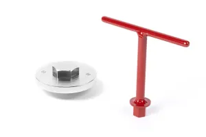
Recommended Kimray Tools
- Removable Seat Tool (if seat is damaged)
- Stem Guide
We’re in a controlled environment, but if you are doing this in-line, you will need to isolate and depressurize the valve first. Before beginning, consult your company’s safety guidelines and use the appropriate personal protective equipment (PPE).
Conversion Components (Standard Ductile Bodies)
2" BP to BPOS Conversion | ||
|---|---|---|
| QTY. | DESCRIPTION | PART |
| 1 | 2” MASTER REPAIR KIT | RYG |
| 1 | 2”-6” BPOS CONVERSION KIT | ROA |
| 1 | TUBE 3/8 SS6 3 BPOS | 72SS6 |
| 2 | ELL 3/8 x 1/4 NPT STEEL | 877 |
3" BP to BPOS Conversion | ||
|---|---|---|
| QTY. | DESCRIPTION | PART |
| 1 | 3” MASTER REPAIR KIT | RYK |
| 1 | 2”-6” BPOS CONVERSION KIT | ROA |
| 1 | TUBE 3/8 OD SS | 73SS |
| 2 | ELL 3/8 x 1/4 NPT STEEL | 877 |
| 1 | CONN 3/8 X 1/4 NPT STEEL | 876 |
4" BP to BPOS Conversion | ||
|---|---|---|
| QTY. | DESCRIPTION | PART |
| 1 | 4” MASTER REPAIR KIT | RYO |
| 1 | 2”-6” BPOS CONVERSION KIT | ROA |
| 1 | TUBE 3/8 OD SS | 73SS |
| 2 | ELL 3/8 x 1/4 NPT STEEL | 877 |
| 1 | CONN 3/8 X 1/4 NPT STEEL | 876 |
6" BP to BPOS Conversion | ||
|---|---|---|
| QTY. | DESCRIPTION | PART |
| 1 | 6” MASTER REPAIR KIT | RYR |
| 1 | 2”-6” BPOS CONVERSION KIT | ROA |
| 1 | TUBE 3/8 304SS 6 BPOS | 74SS |
| 2 | ELL 3/8 x 1/4 NPT STEEL | 877 |
How to Disassemble a Back Pressure Regulator for Outside Supply Conversion
- Using a 9/16” wrench, remove the adjustment screw and discard the washer and packing seal.
- Next, remove and set aside the pressure gauge and all the breather plugs from the bonnet, upper housing and lower housing. (Note: If the breather plug from the lower housing shows signs of corrosion, a spare breather plug is included in the conversion kit. If the breather plug is still in a serviceable condition, it can be reused.)
- Loosen all the tubing connectors.
- Remove the bonnet bolts with a 9/16” wrench and rotate the pilot housing to remove the tubing.
- Remove and discard the tubing as well as the elbows from the main body and filter body.
- Remove the upper bonnet, upper spring plate, spring, lower spring plate, and spacer ring.
- Then remove the pilot housing from the upper housing. If it’s stuck from rust or corrosion, you can use a flathead screwdriver to separate them.
- Turn the pilot housing over and use a 9/16” socket wrench to remove and discard the pilot seat, pilot plug, spring and diaphragm.
- Use channel locks to separate the diaphragm nut from the diaphragm plate. You could also use a vise instead if you have one available.
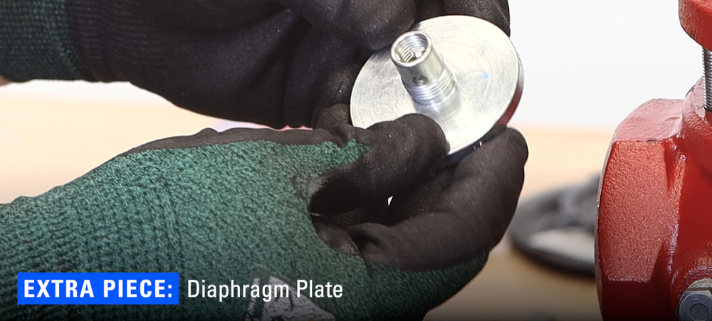
- Remove and discard the diaphragm. Set the diaphragm plate aside. It will be an extra piece that will not be used for this conversion. This can also be used to convert other Kimray products to non-vent configurations. Set the diaphragm plate aside. It will be an extra piece that will not be used for this conversion. This can also be used to convert other Kimray products to non-vent configurations.
- Use the 9/16” socket wrench to remove and discard the (113) pilot seat and gasket from the upper housing.
- Now, remove all the upper housing bolts and then remove the upper housing. You may have to use a flathead screwdriver to separate them.
- Once you’ve removed the upper housing, discard the diaphragm.
- Remove the lower housing from the body. Again, you may need to wedge a flathead screwdriver between the housings to pry them apart.
- Carefully discard the oil in the lower housing.
- Remove and discard the gasket from the body. This may be attached to the lower housing instead.
- If you have the Kimray seat removal tool, use it to take out the removable seat and inspect it for signs of corrosion, pitting or scoring. This piece is not included in your repair kit, so if it does need to be replaced, you’ll need to order a new one.
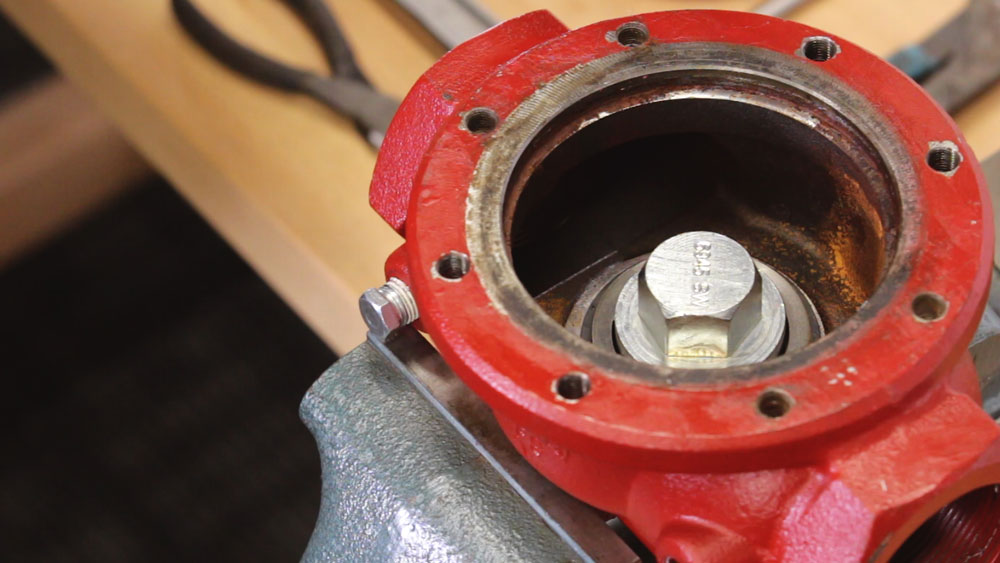
- If you do not have the Kimray seat removal tool, inspect the seat for damage, but don’t try to remove it from the body. You’re more likely to further damage the seat by prying it out.
- If you take out the removeable seat, remove and discard the gasket from it. This piece is included in your repair kit.
- Put the diaphragm plate of the lower housing into a vise.
- Use a 9/16” wrench on the lock nut to remove the ratio plug, seat and seat disc. If your main stem begins to unthread, the lock nut may not come loose. You may have to use soft jaws on the main stem in your vise to keep it from moving.
- Discard the lock nut and seat.
- Keep the ratio plug and seat disc. - Using a pick, remove and discard the two Teflon backups and the O-ring from the lower housing.
- Put the pilot housing into a vise, then remove the filter cap and its contents. Remove and discard the O-Ring from the filter cap.
- Insert a pick in the gauge port to push the screens out, then use needle nose pliers to finish removal.
- Remove the filter body with channel locks.
- Remove the nipple with a 5/8” wrench, but save this piece for assembly.
How to Inspect and Clean a Back Pressure Regulator
- Inspect the body for rust or debris that might clog your filter when the valve is in service.
- Use a putty knife, Emery cloth, or flat head screwdriver to clean the gasket surface on top of the body.
- Use compressed air to clear the sense line communication port.
- Check for any debris from the breather plug communication port of the lower housing.
- Clean the upper housing – clear any debris from the gasket seating area by using an Emery cloth or a flathead screwdriver to scrape out the old gasket.
- To ensure there are no obstructions, insert a small screwdriver or an awl into the breather plug communication port until you can see it inside the upper housing. Also check the port going to the diaphragm.
With the valve fully disassembled, now is a good time to organize your workspace and open your Kimray Repair Kit to prepare for assembly.
How to Reassemble a Back Pressure Regulator for Outside Supply
- If you took out the removable seat, put on the new gasket from the repair kit.
- Apply grease to the gasket and install the removable seat into the body with the Kimray Seat Removal Tool to 30 ft-lbs. Do not overtighten the seat. This could cause damage to the gasket.
- Stretch one of the Teflon backups slightly to make it look like a spring.
- Insert one end of the backup into the lower housing and use a pick to rotate it counterclockwise until it’s fully installed.
- Pinch and fold the o-ring to make it easier to install.
- Push the O-ring and first Teflon backup all the way down to the bottom of the lower housing channel to make room for the last backup.
- Again, uncoil the Teflon backup, then insert it into the lower housing and rotate counterclockwise.
- Add grease to the Teflon backups and O-ring.
- Put the diaphragm plate in the vice.
- Put on the Kimray stem guide. When you install the lower stem, it's best to use a Kimray stem guide to avoid sheering the O-ring.
- Fully insert the stem into the lower housing, then remove the stem guide.
- Install the seat disc, new seat and ratio plug.
- Put on the locknut. When tightening the locknut, it’s critical to not over-tighten, because it can deform the seat. Tighten it to the point where the seat disc no longer rotates.
- Remove the lower housing from the vise and make sure that the lower stem can move freely before continuing.
- Put the (5259P) diaphragm on the NEW (116) diaphragm plate.
- Hand-thread the diaphragm nut to the plate.
- Secure the plate in a vise. Use the spacer ring around the diaphragm to know how much to tighten it with channel locks. If it is too tight, the diaphragm will be distorted and not fit correctly inside of the spacer ring.
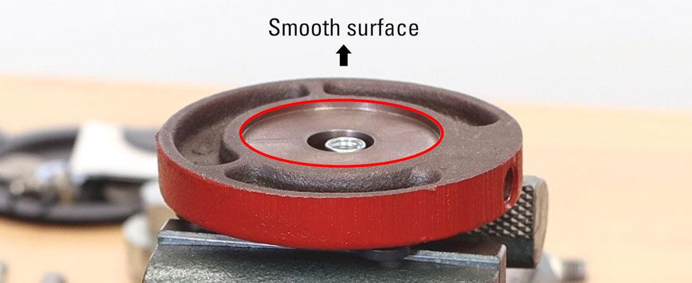
- Place the first diaphragm housing over this assembly with the smooth surface facing up.
- Thread a (110) diaphragm on the seat extension.
- Then thread the seat extension into the diaphragm plate by hand and then tighten until snug.
- Place the spacer on the opposite side with the part number facing up.
- Put your original diaphragm housing on top, smooth side up.
- Put the (110) diaphragm on the (113) pilot seat.
- Thread the seat onto the seat extension by hand then tighten the pilot seat with a 9/16” socket wrench being careful not to overtighten it.
- Make sure the (110) diaphragm is centered in the pilot housing.
- Remove the diaphragm housing assembly from the vise and replace it with the body.
- Lubricate the gasket surface of the lower housing with grease. Place the gasket on that surface, then grease the top.
- Now install the lower housing into the body. The port will be on the same side as the ports on the valve body.
- Fill the lower housing with any kind of light gravity motor oil until the communication hole to the lower stem is fully submerged.
- Install the main diaphragm, bevel side down, then mount the upper housing on the body with the port facing downstream.
- Hand-start the bolts. Tighten down two opposite bolts evenly, then alternate with a star pattern, just like you would lug nuts on a wheel.
- Put the (108) conical spring in the valve body with the smaller end facing up.
- Put the new (118) gasket on the (565) pilot seat.
- Pick up the (565) pilot seat with the pilot plug by the small ball. thread it down by hand before tightening gently with socket wrench. Do not over-tighten it because you could tear through the gasket.
- Verify that the pilot plug can move freely and returns with the spring tension before continuing. If you've done everything correctly, you should feel the resistance of the spring as you push the pilot plug down. Never use any grease or oil in the pilot plug area. Any debris could keep the pilot plug from seating correctly.
- Place the diaphragm housing assembly on top of the upper housing.
The lower diaphragm housing port will face the Kimray logo on the valve body.
The upper diaphragm housing port will face the upstream side of the valve. - Install the O-ring on the filter cap.
- Insert the six filter screens into the body.
- Hand thread the filter cap into the filter body.
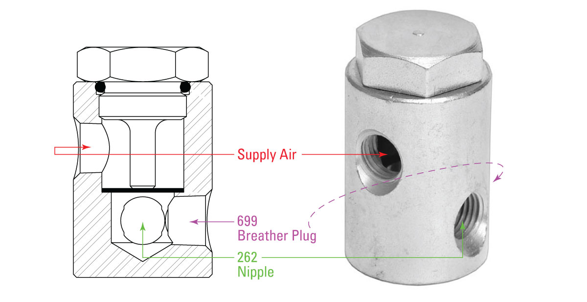
- Apply Loctite to the nipple and hand thread it into the upper housing port.
- Apply Loctite to the other end of the nipple and thread on the filter body. You will use the port that has no NPT on the opposing side.
- Use channel locks on the filter to fully tighten it. The filter cap will be facing the same side as the sensing ports. Your supplied air to the regulator will come into this filter, so it’s important to clear the airline of any debris before connecting.
- Now you can fully tighten the filter cap.
- Install a (699) plug on the top of the filter body with a 9/16” wrench.
- Add grease to the upper diaphragm plate.
- Replace the lower spring plate, spring and upper spring plate.
- Grease the top of the upper spring plate.
- Place the bonnet with the NPT facing the body sensing ports. Hand-start the new longer bolts, but do not tighten them all the way.
- Apply Loctite to the elbow and thread it into the upstream sensing port.
- Apply Loctite to the nipple with the hex and hand thread it into the upper diaphragm housing.
- Apply Loctite to the other end of the nipple and hand start the (2000) Tee fitting.
- Tighten with channel locks or a large crescent wrench making the Tee fitting ports vertical.
- Apply Loctite to the treads of the second elbow and install it into the bottom port of the Tee fitting.
- When tightening this fitting, stop with the tubing connector approximately facing the bolts of the upper housing. The final tightening will come once the tubing is in place.
- Now bend and fit your tubing to connect the two elbows.
- Then, tighten the fittings.
- Now you can fully tighten the bonnet bolts.
- Install all three breather plugs in the bonnet, pilot housing, and lower housing. Tighten them so that the hole is pointing down or at an angle so that it is harder for rain and debris to get inside and clog the breather plug.
- Apply Loctite to the gauge and install it on the top port of the Tee.
- Lastly, insert the adjustment screw with the new washer and packing seal.
Because this repair kit can be used for other products, there will be two remaining pieces that will not be used:
- Gasket (276)
- Diaphragm (6520)
Your back pressure regulator is now ready to use with an outside supply source. If you have any questions about any part of this repair process or the custom Kimray tools used, reach out to your local Kimray store or authorized distributor.
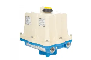
We have other solutions available to help you meet your company’s ESG goals, including electric actuators and pilots, non-vent control valves and more. For more information, check out our emissions solutions guide.