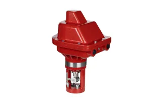
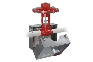
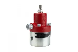
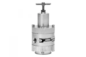
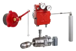
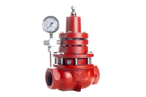
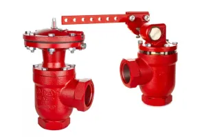
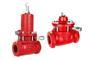
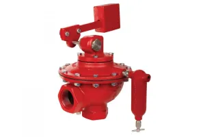
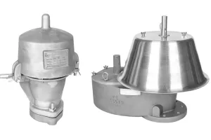
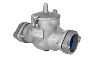
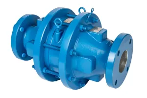
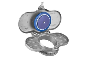
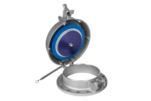
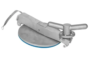
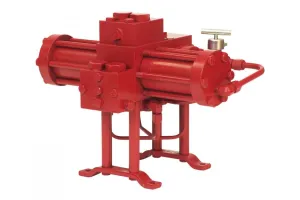

Low Pressure Regulators perform the same function as standard regulators but have lower control ranges.
Kimray has three primary models:
- Standard
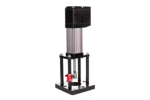
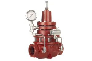
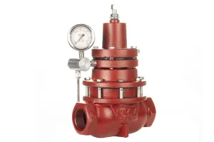
- Vacuum
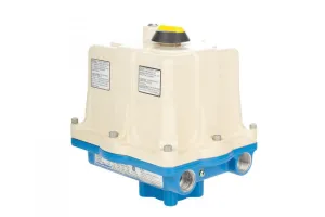
- Outside Supply (formerly known as “to atmosphere”)
The “atmosphere” design has been recently modified and renamed the Low Pressure Back Pressure Outside Supply.
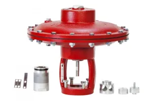
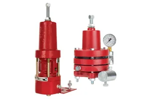
In this video, we’ll be showing how to install a Kimray Master Repair Kit for the 2” standard and “-to atmosphere” outside supply low pressure back pressure regulators.
Tools & Components Needed
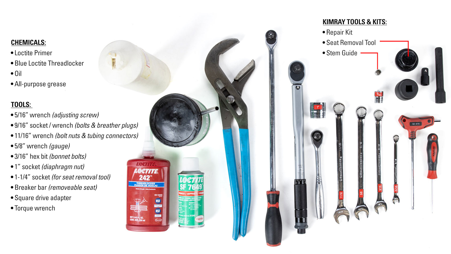
For the 2” model, you’ll need the following tools, components and chemicals:
Tools
- 5/16” wrench (adjusting screw)
- 9/16” socket / wrench (bolts & breather plugs)
- 11/16” wrench (bolt nuts & tubing connectors)
- 5/8” wrench (gauge)
- 3/16” hex bit (bonnet bolts)
- 1” socket (diaphragm nut)
- 1-1/4” socket (connecting to seat removal tool)
- Breaker bar (removable seat)
- Square drive adapter
- Torque wrench
- Pick
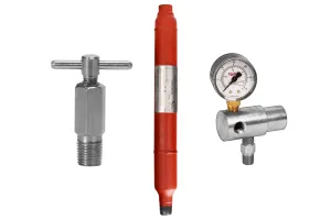
Kimray Components
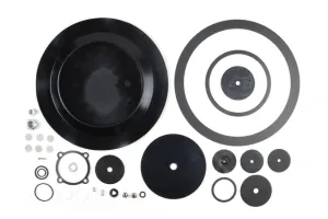
- Repair Kit
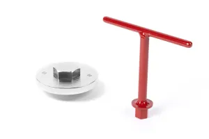
- Seat Removal Tool
- Stem Guide
Chemicals
- Primer
- Blue Loctite
- Oil
- Grease
| Size | Master Repair Kit | Tool | Trim Size | |
| 1/2" Trim | 1" Trim | |||
| 2" | RYI Corrosive: RYIS6 | Seat Removal Tool | N/A | 6945SW 272SW |
| Stem Guide | 1852 | |||
| 1-5/8" Trim | 3" Trim | |||
| 3" | RYM Corrosive: RYMS | Seat Removal Tool | Ductile: 1219SW Steel: 1219HTSW | 6945SW 273SW |
| Stem Guide | 1853 | |||
| 2" Trim | 4" Trim | |||
| 4" | RYQ Corrosive: RYQS6 | Seat Removal Tool | Ductile: 1220SW Steel: 1220HTSW | 6947SW 274SW |
| Stem Guide | 1854 | |||
| 3" Trim | 6" Trim | |||
| 6" | RYT Corrosive: RYTS6 | Seat Removal Tool | Ductile: 1221SW Steel: 1221HTSW | 6948SW 275SW |
| Stem Guide | 1855 | |||
CAUTION: The procedures demonstrated in this video are intended for general informational purposes only. Always follow your company’s safety requirements, policies, and applicable regulations when performing any maintenance or repair.
Before starting any repair or maintenance activities:
Review and follow all WARNING and CAUTION notes found in the Kimray Installation, Operation, and Maintenance (IOM) guide for your specific product.
Wear all required personal protective equipment (PPE), including approved eye protection, steel toe safety shoes, and nitrile gloves to protect against exposure to chemicals and other hazardous materials.
Failure to use appropriate PPE or follow proper procedures can result in serious injury or death.
WARNING: Before any service, be certain that the valve is fully isolated and that all pressure upstream and downstream has been relieved. Use bypass valves or fully shut off the process. Be sure that any operating or instrument gas lines have been disconnected. Never assume that a check valve is fully blocking the downstream line. Never tighten any fitting or the main connections to the regulator while there is pressure on the line.
How to Disassemble a Low Pressure Back Pressure Regulator
Before you begin, it can be helpful to mark a line down each section of your regulator so that during assembly, the markings can be easily aligned back in the same orientation.
Adjusting Screw, Gauge, Tubing, Filter and Bonnet
- To begin disassembly, use a 5/16” wrench to loosen or remove the adjusting screw to release spring tension.
- Next, remove the gauge with a 9/16” wrench.
- Use a 3/16” hex key wrench or socket to remove the six bonnet bolts and set the bonnet aside.
- Remove the spring plate and spring.
- Then, remove and discard the gasket. It may be in the housing or stuck to the bonnet.
- Remove the diaphragm nut with a 1” socket wrench.
- Remove and discard the O-ring; it will either be on the stem or have come off with the nut.
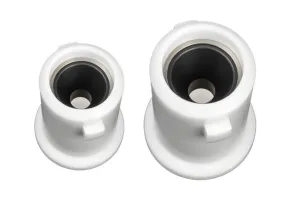
Upper & Lower Pilot Housings
- With a 9/16” and 11/16” wrench, remove the bolts and nuts, then remove the upper pilot housing.
- Remove and keep the diaphragm plate.
- Discard the diaphragm.
- Remove and keep the lower diaphragm plate.
- Use an 11/16” wrench to loosen the tubing connectors.
- Use a 9/16” socket wrench to break torque on the four bolts from the housing.
- Then remove the tubing.
- You can disconnect the elbows if they need to be replaced or cleaned but otherwise leave them attached.
- Fully unthread and remove the bolts from the housing, discarding the four gaskets.
- Discard the booster spring.
- Use a 9/16” socket to remove the pilot seat. Discard the seat and the attached gasket.
- Remove the breather plug from the upper housing with a 9/16” wrench.
- Use a 9/16” socket to remove the upper housing bolts.
- Then remove the upper housing.
- Remove and discard the diaphragm. It may be stuck to the housing.
Lower Housing
- Remove the lower housing, if it’s stuck you may need a flathead screwdriver or similar tool to remove it.
- Properly discard the oil in the lower housing, then set it aside.
- Remove and discard the lower housing gasket. It may be on the lower housing or the valve body.
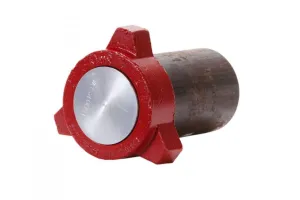
Removable Seat
Next, we’ll look at the removable seat. You can inspect it in place for signs of corrosion or pitting. If there’s no obvious wear and you don’t have the Kimray seat wrench, you can leave it in place. Without the correct Kimray tool to remove it, you may end up damaging the seat.
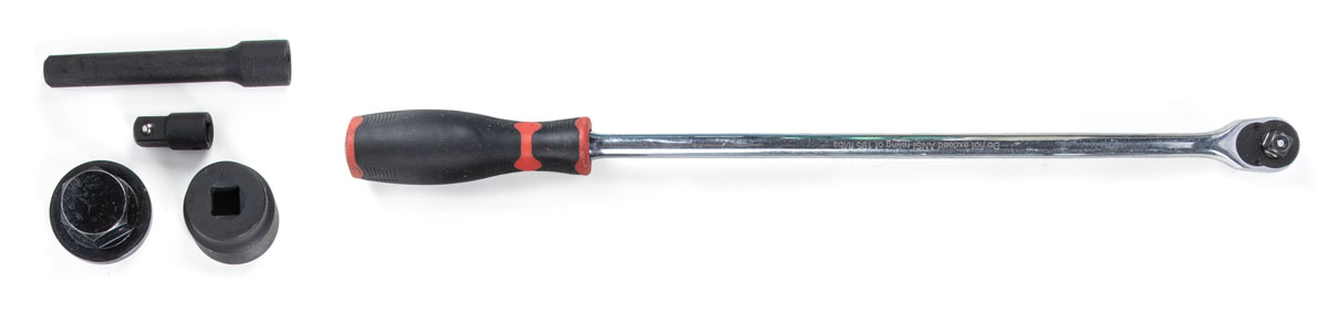
- Place the Kimray seat tool on the seat and use a 1-¼" socket and square drive adapter with a breaker bar to remove it.
- Remove and discard the gasket from the seat.
- Replace the valve body with the lower housing in the vise.
Lower Housing (cont.)
- Put the lower housing into the vise by the diaphragm plate.
- With a 9/16” socket, remove and discard the nut.
- Remove the seat disc, seat and ratio plug. Discard the seat but keep the seat disc and ratio plug.
- Lift off the lower housing from the stem.
- Inspect the stem and diaphragm plate, but if they’re in good condition, you can leave them attached.
- Using a pick, remove and discard the O-ring and two backups from the lower housing.
Upper Pilot Housing (cont.)
- Place the lower pilot housing in the vice.
- Hold onto the stem hex with one hand and use a 9/16” socket on the pilot seat to separate the components.
- Discard the spring from the stem, but keep the stem
- Discard the seat, pilot plug, and diaphragm.
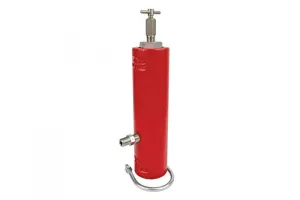
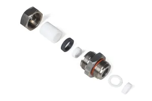
Filter
- Remove the filter cap with an adjustable wrench.
- Remove and discard the O-ring from the cap.
- Using a pick and needle nose pliers, remove and discard the stack of 6 filter screens.
How to Disassemble a Low Pressure Back Pressure to Outside Supply Regulator
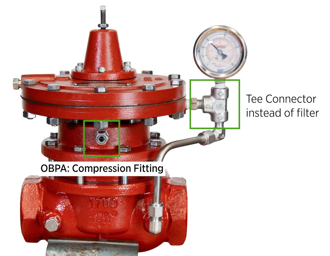
There are only a few differences for the LPBPOS (formerly OBPA) disassembly.
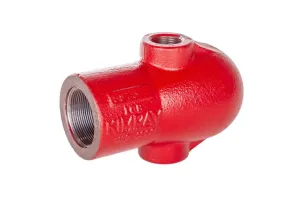
- The first difference is that instead of a filter, there will be a Tee connector to remove.
- Once you separate the stem and seat, the pilot seats will be reversed from the LPBPOS model. This does not impact the disassembly process; it will just look a little different.
- Instead of a breather plug, you’ll remove the compression fitting from the upper housing.
Inspection & Cleaning
With the regulator disassembled, open the repair kit to prepare for assembly.
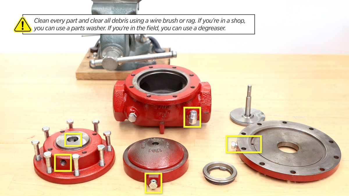
Clean every part and clear all debris using a wire brush or rag. If you’re in a shop, you can use a parts washer. If you're in the field, you can use a degreaser.
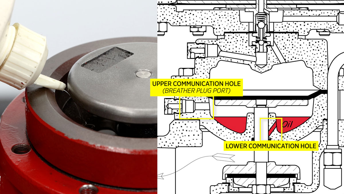
Make sure that all communication ports such as in the upper housing and the breather plugs have been cleaned thoroughly and that any thread tape has been removed.
Low Pressure Back Pressure Regulator Assembly with master Repair Kit
Filter Assembly
- From where we left off in disassembly with the filter body in a vise, insert the six (#619) filter screens. Use a pick or small flathead screwdriver to push them into place.
- Install the (#155) O-Ring onto the filter cap.
- Lightly apply oil to the O-Ring and install the filter cap onto the filter body with an adjustable wrench.
- If you removed the connector or elbow from the filter, apply primer and blue Loctite to the threads before installing them.
Pilot House Assembly
- Place the stem into the vise with the female threaded end facing up.
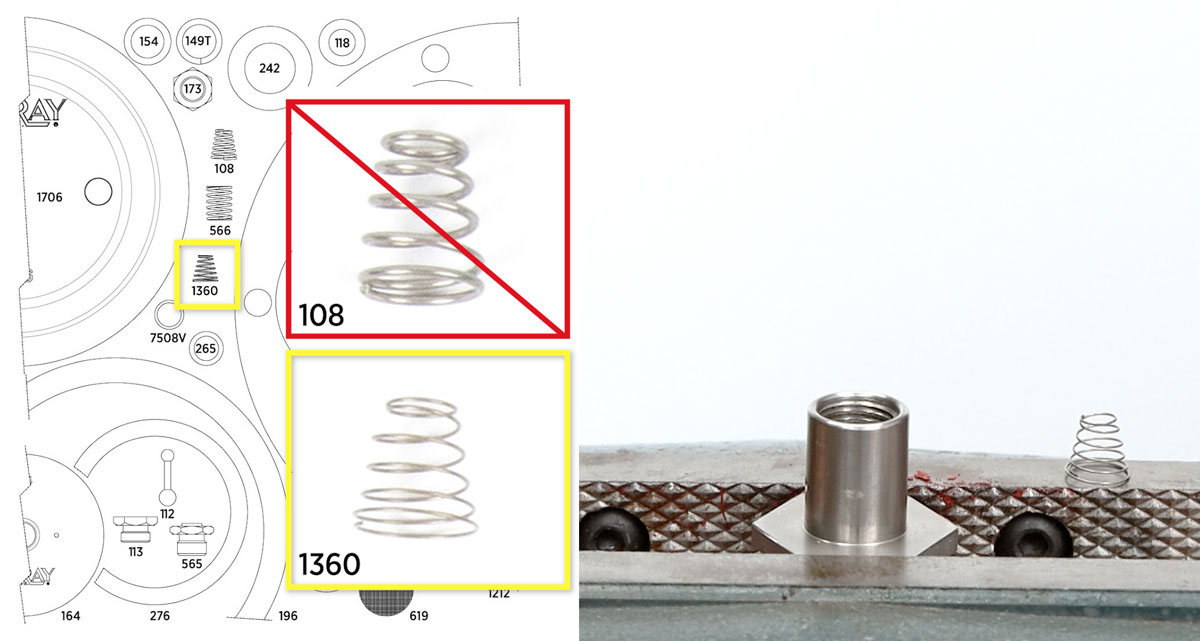
- Place the (#1360) conical spring, wide end down into the stem.
- Place the lower pilot housing onto the stem, painted side facing up.
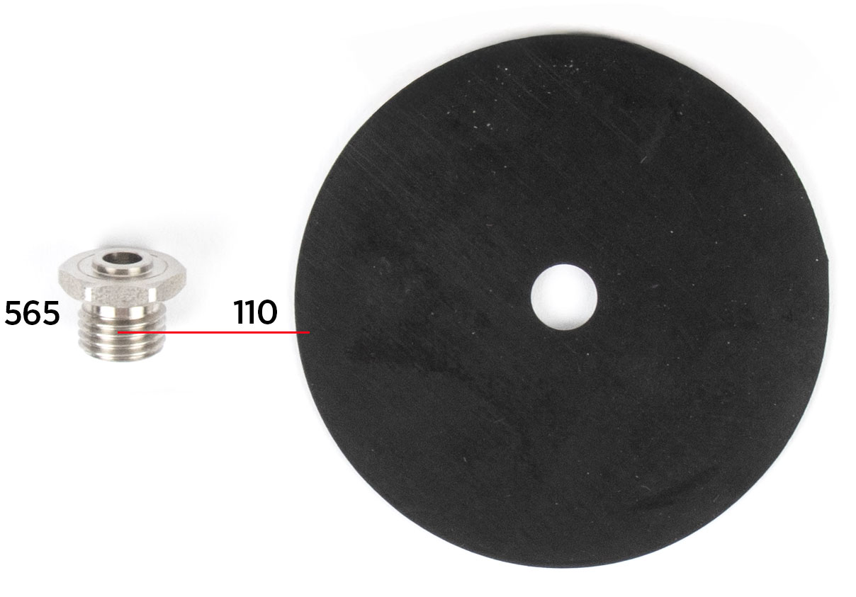
- Install the (#110) diaphragm onto the (#565) pilot seat.
- Place the (#112) pilot plug into the pilot seat, small ball first.
- Holding this assembly by the small ball of the pilot plug, hand start it into the pilot housing.
- Fully tighten it with a 9/16” socket, but do not over tighten it.
- This assembly should have play in it when removed from the vise.
Lower Housing
- Place the diaphragm plate, with the stem attached, into the vise.
- Slightly stretch a (#149T) backup out like a spring. Insert one end into the lower housing and use a pick to rotate it counterclockwise until it’s fully installed.
- Next, pinch and fold the (#154) O-ring to install it into the lower housing.
- Push the O-ring and backup down to the bottom of the channel to make room for the second backup.
- Insert the second (#149T) backup into the lower housing and rotate counterclockwise as before.
- Add grease to the backups and O-ring.
- Place the Kimray stem guide onto the stem. It's best to use a Kimray stem guide to avoid shearing the O-ring when installing the lower housing over the stem.
- Grease stem guide
- Put on the lower housing, then remove the stem guide.
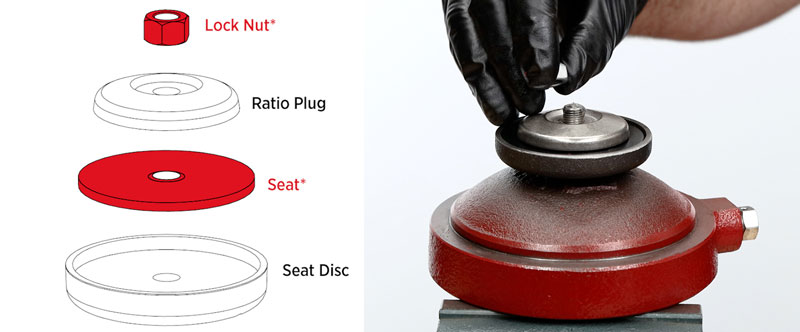
- Next, place the seat disc on the stem.
- Then add the new (#164) seat.
- Place the ratio plug on top.
- Apply all-purpose grease to the threads of the stem
- Hand start the new (#173) lock nut threads before fully tightening with a 9/16” wrench to the point where the seat disc no longer rotates. Do not overtighten.
- Apply all-purpose grease to the lower housing shoulder.
- Place the (#196) gasket on top, then apply grease to the gasket.
- Remove the lower housing from the vise and make sure that the lower stem can move freely.
Removable Seat
 Place the valve body in the vise.
- Add grease to the threads of the removable seat.
- Then install the (#276) gasket onto the seat.
- Apply grease to the top of the gasket as well.
- Install the removable seat with the Kimray seat tool.

Lower Housing Assembly
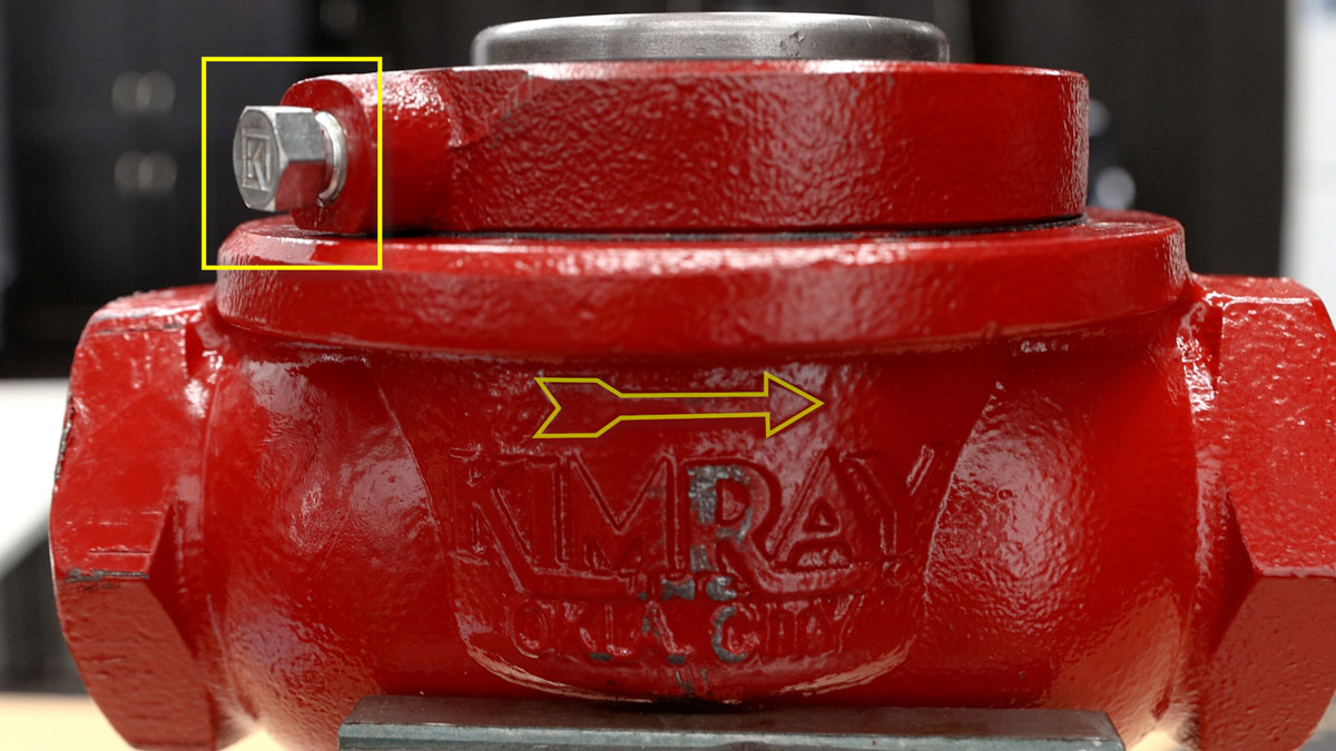
- Insert the lower housing into the body. Make sure the breather plug hole aligns with the back side of the flow arrow.
- Add all-purpose oil to the housing until the oil is above the lower communication hole and below the upper communication hole.
- Being careful not to pinch your fingers, push down the diaphragm plate directly on top.
- Install the main (#1706) diaphragm onto the lower housing assembly, beveled side down.
Upper Housing, Lower Seat, & Tubing
- Place the upper housing on top of the lower housing, aligning the breather plug port between the outlet holes in the body.
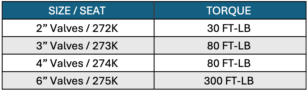
- Start the bolts by hand, then fully tighten them using the torque star pattern. For 2”, 3” and 4” regulators tighten to 25-30 ft-lbs.
- Install the breather plug using a 9/16” wrench. Turn it so the opening faces down.
- Place the (#118) gasket on the (#113) pilot seat.
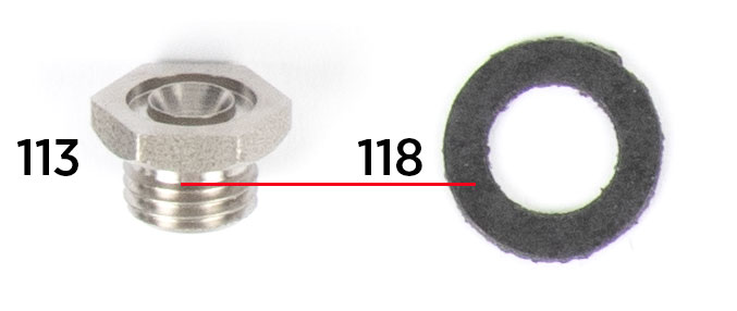
- Hand start the (#113) pilot seat then fully tighten with a 11/16” socket. Do not overtighten.
- Install the (#566) “booster” spring
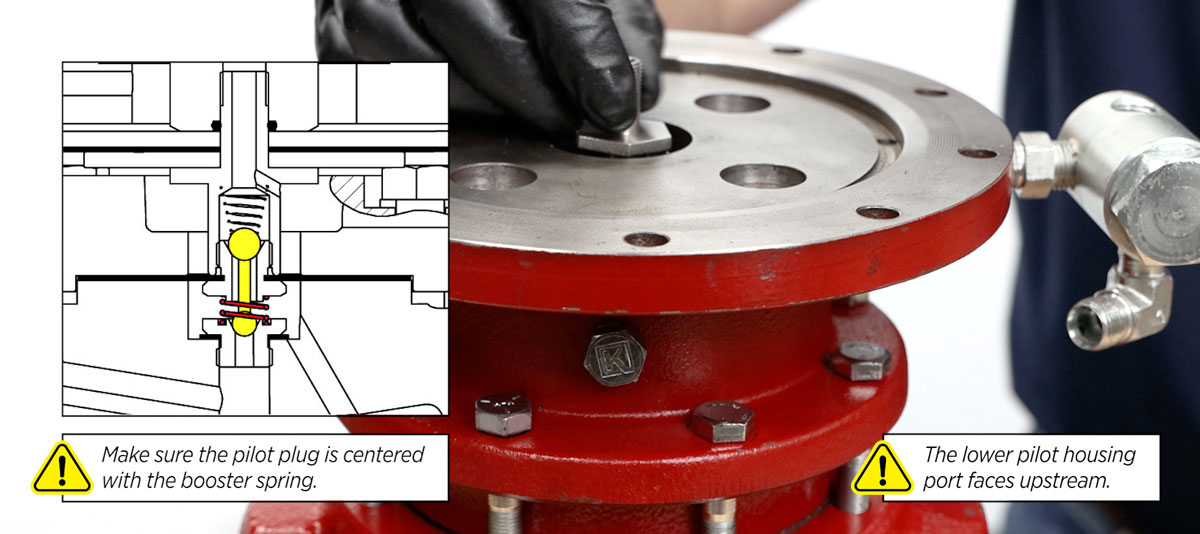
- Place the pilot housing assembly on the upper housing. Make sure the pilot plug is centered with the booster spring. Align the housing so the port and filter are facing upstream.
- Install a new (#242) gasket onto each of the bolts.
- Insert the tubing into the elbow connectors.
- Fully tighten the bolts to 20 ft/lbs. with a 9/16” socket in a crisscross pattern.
- Start the compression nuts onto the elbows by hand and then fully tighten with an 11/16” wrench.
Lower Pilot Housing, Upper Pilot Housing & Bonnet
- Install the lower diaphragm plate.
- Then the (#1212) diaphragm.
- Followed by the upper diaphragm plate.
- Install the upper pilot housing, aligning the bolt holes and diaphragm holes. Align the NPT port to face downstream.
- Install the lifting rings 180 degrees from each other. Use a 9/16” and 11/16” wrench to install the bolts and nuts into the housing.
- Place the (#265) O-Ring on the stem and apply grease.
- Thread on the diaphragm nut and then torque to 60-70 in-lbs. with a 1” socket.
- Grease the surface where the gasket will go, then install the (#1216) gasket.
- Grease the top of the gasket also.
- Put the spring and spring plate on the diaphragm nut, ensuring the pivot side of the plate is facing up.
- Lightly grease the pivot on the spring plate.
- Attach the bonnet and tighten with a 3/16” hex key wrench or socket in a crisscross pattern. Kimray recommends tightening to 15 ft-lbs.
- Finish by installing the adjusting screw with a 5/16” wrench.
Gauge
- Apply primer and Loctite to the threads on the gauge.
- Then install the gauge into the filter with a 9/16” wrench.
This completes the repair process. If you have any questions, contact Kimray Technical Sales Support.