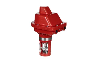
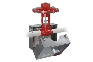
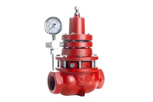
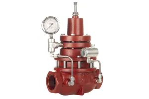
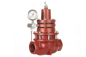
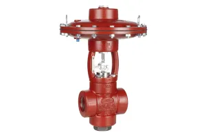
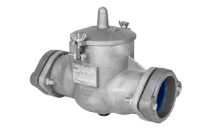
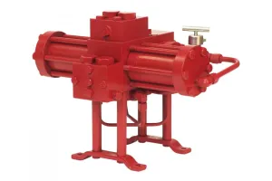
In this video, we’ll show you how to repair a 2" Cage Guided High Pressure Control Valve, as well as how to easily change the actuator failure position.
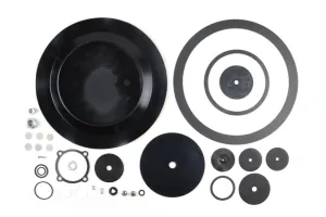
For this job, you will need the following tools, equipment, and chemicals. There are also a couple of commonly replaced parts like the diaphragm and trim set pieces that are not in the repair kit.
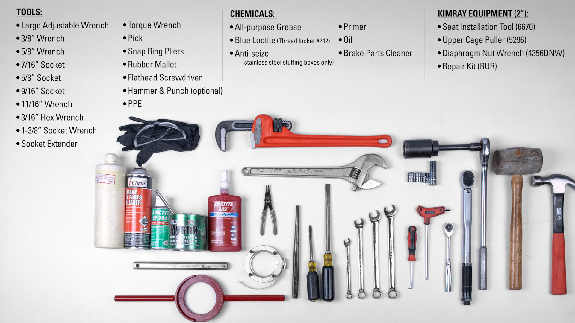
Tools
- Large Adjustable Wrench (adjusting screw & stuffing box)
- 3/8” Wrench (upper stem)
- 5/8” Wrench
- 7/16” Socket (travel indicator)
- 5/8” Socket (piston assembly bolt)
- 9/16” Socket (body bolts & breather plug)
- 11/16” Wrench (bonnet bolt nuts)
- 3/16” Hex Wrench (cage puller)
- 1-3/8” Socket Wrench + Extender (lower adjusting screw)
- Torque Wrench (body bolts)
- Pick
- Snap Ring Pliers
- Rubber Mallet
- Flathead Screwdriver (cage puller and housing separation)
- Hammer & Punch (optional, to remove diaphragm nut)
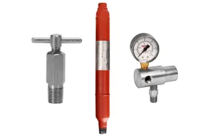
Kimray Equipment (2")
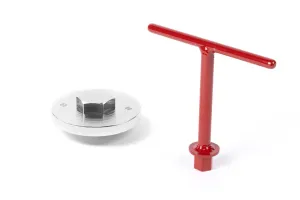
- Seat Installation Tool (2IN - #6670)
- Upper Cage Puller (2IN - #5296)
- Diaphragm Nut Wrench (2IN - #4356DNW)
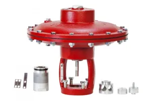
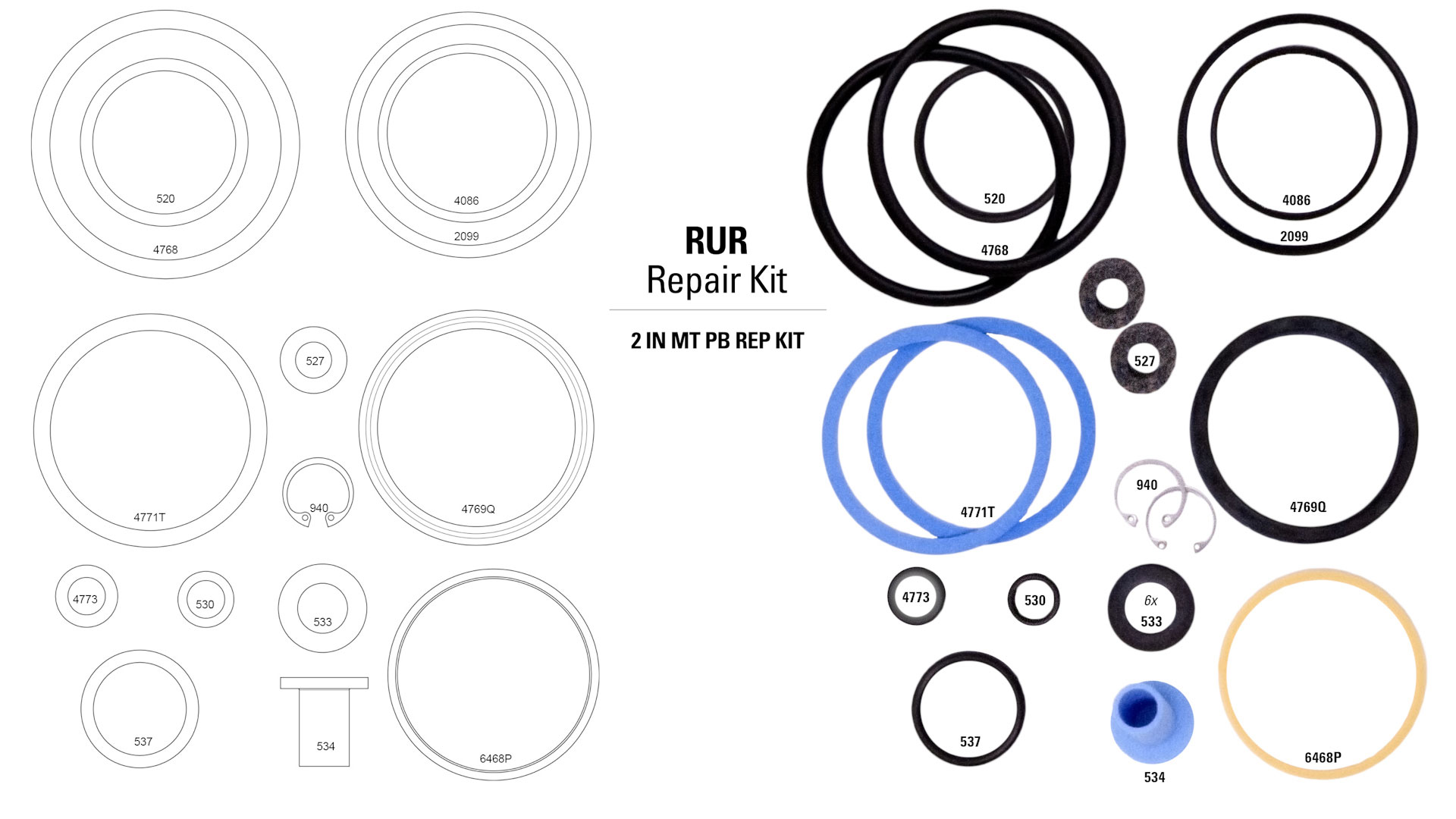
- Repair Kit (2IN - RUR)
Commonly Replaced Parts (not in repair kit)
- Diaphragm
- Trim Set
Chemicals
- All-purpose Grease
- Blue Loctite/Thread locker #242
- Primer
- Oil
- Brake Parts Cleaner
- Anti-seize (for stainless steel stuffing boxes only)
Nitrile gloves are highly recommended when working with and handling greases and chemicals to prevent skin irritation. Before any service, be certain that the valve is fully isolated and that all pressure upstream and downstream has been relieved. Use bypass valves or fully shut off the process. Be sure that any operating or instrument gas lines have been disconnected.
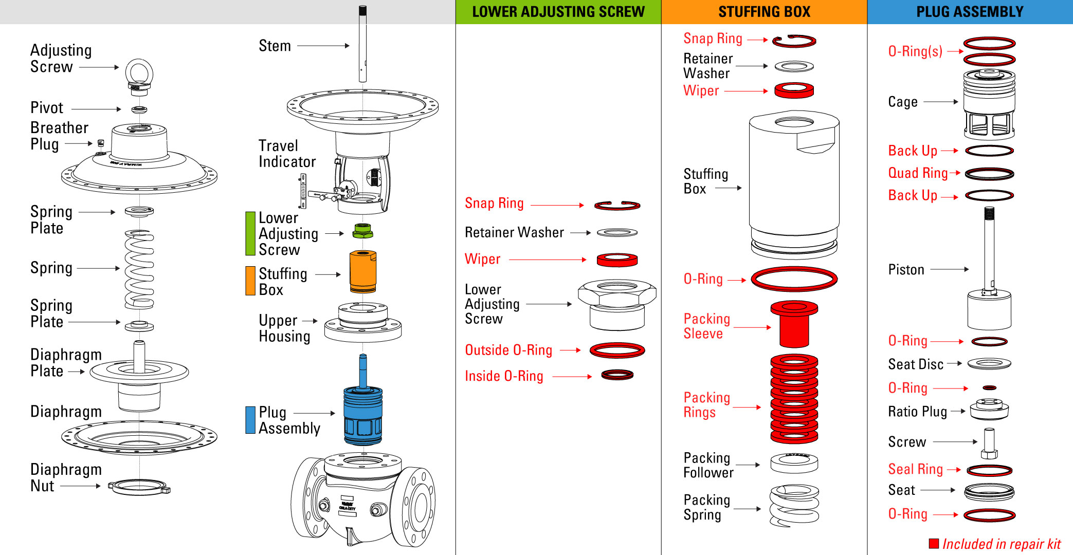
How to Disassemble a Cage Guided High Pressure Control Valve
Adjusting Screw, Pivot, Breather Plug, Bonnet, Spring Plates & Spring
- Start by removing the adjusting screw with an adjustable wrench.
- Remove the pivot from the adjusting screw. Sometimes the pivot will separate and sit on top of the spring plate. If so, we’ll remove it later.
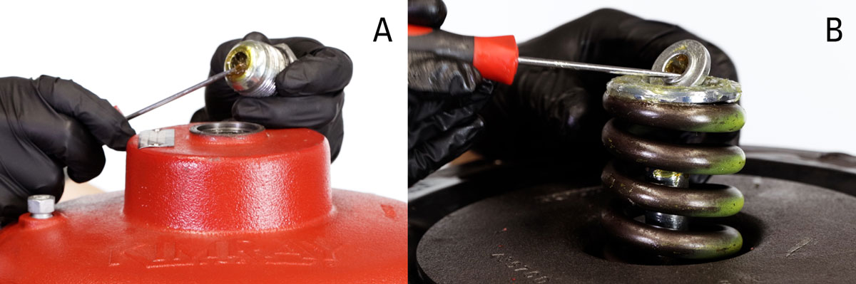
- Remove and discard the O-ring from the adjusting screw.
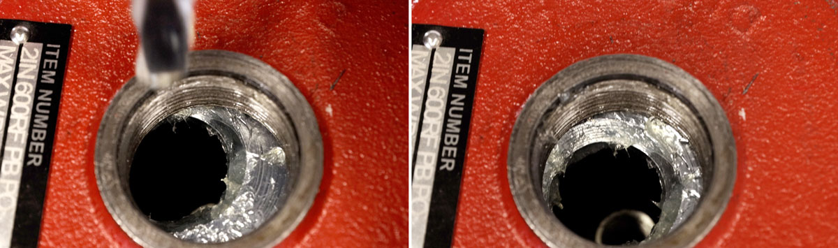
- Next, use a 9/16” wrench to remove the breather plug.
- Use a 9/16” wrench or socket and 11/16” wrench to remove the bonnet bolts, then remove the bonnet.
- If the pivot separated from the adjusting screw, it can now be removed, followed by the upper spring plate, spring, and lower spring plate.
Travel Indicator
- Remove the bolts from the travel indicator block with a 7/16” wrench.
- Then remove the block and indicator tag from the stem.
Diaphragm Assembly
- Next, use a 3/8” wrench on the flats of the upper stem while you unthread the diaphragm plate.
Yoke & Lower Adjusting Screw
- Use a 9/16” wrench to remove the four bolts from the yoke base.
- Slide the yoke up from the upper housing and empty the oil into an appropriate container.
- Flip the yoke over and remove the lower adjusting screw with a 1-3/8” socket and extension.
- Slide out the upper stem from the lower adjusting screw.
- Use a pick to remove and discard the large O-Ring on the outside of the adjusting screw as well as the smaller O-Ring inside.
- Use snap ring pliers to remove and discard the snap ring.
- Next, remove the retainer washer, but keep this piece.
- Last, remove and discard the wiper.
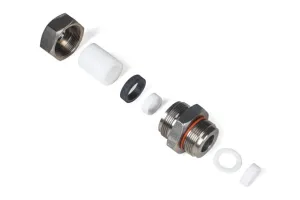
Stuffing Box
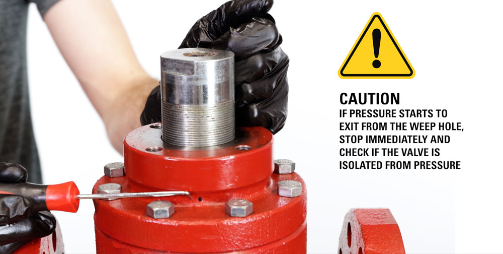
- Use a large adjustable wrench only on the flats of the stuffing box to unthread the assembly by turning counterclockwise.
Use caution—if pressure starts to exit from the weep hole, stop immediately and check if the valve is isolated from pressure.
- Remove the spring. This may be inside the valve body.
- Using a pick, pull out and save the packing follower.
- Turn the stuffing box over and use snap ring pliers to remove and discard the snap ring.
- Remove and save the retainer washer.
- Then discard the felt wiper.
- Use a pick to remove and discard the packing rings and sleeve.
- Remove and discard the outside O-ring with a pick.
Upper Housing
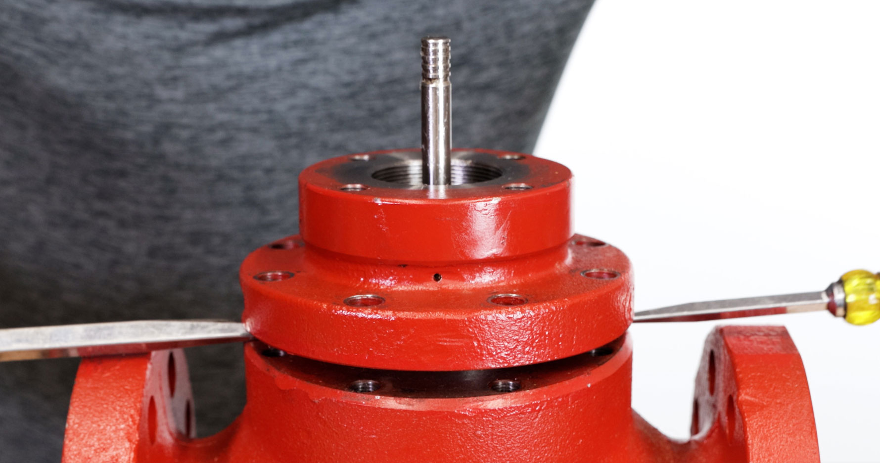
- Next, use a 5/8” wrench to remove the upper housing from the valve body.
- You may need to use one or two flathead screwdrivers or a similar tool to pry them apart.
Plug Assembly
The plug assembly includes the cage and piston assembly inside of it.

- To remove the assembly from the body, you may be able to simply pull up on the stem. You can wrap the stem in a clean rag for a better grip.
- If that doesn’t work, first remove the O-Ring from the cage assembly. Then use two flathead screwdrivers to lift out the cage. Be very careful to not to damage the cage. If the cage loses its shape, it will have to be replaced.
- We recommend using the Kimray cage puller. With the O-ring removed, mount the cage puller by sliding each half over the cage, followed by the clamp and then tightening the screw. Tighten the bolts on the cage puller one at a time to lift the cage assembly out of the body.
- Remove the second O-ring from the cage assembly.
- Remove the O-ring on the seat. This may also have gotten stuck in the valve body.
- Put the plug assembly in a vise, being careful not to damage it by overtightening. You could also use a pipe wrench to grip the cage instead of a vise if you choose.
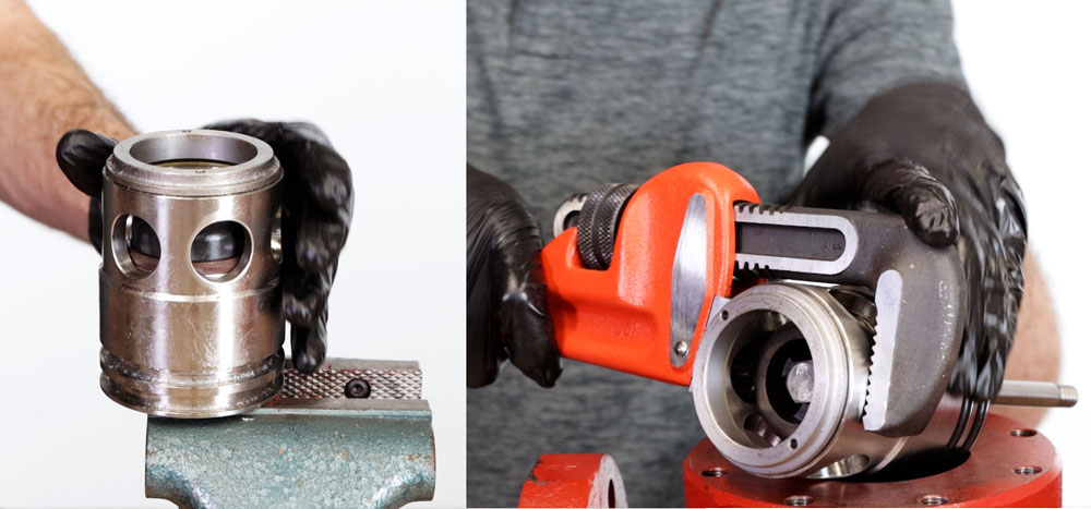
- Use the Kimray seat removal tool to remove the seat. If you do not have this tool, use caution as it can be damaged if removed improperly.
- Remove and discard the seal ring from the seat.
- Next, separate the piston assembly from the cage. You may need to use a rubber mallet for this.
- Put the two flats of the piston assembly into a vise with brass jaws.
- Use a 5/8” socket wrench to unthread the bolt from the ratio plug.
- Remove the ratio plug and seat disc.
- Discard the O-ring. It may be on the piston instead.
- Remove and discard the small O-ring in the piston.
- Remove the quad ring and two backups inside the cage.
Diaphragm Assembly
- The diaphragm needs to be inspected for any abnormal wear like punctures or swelling.
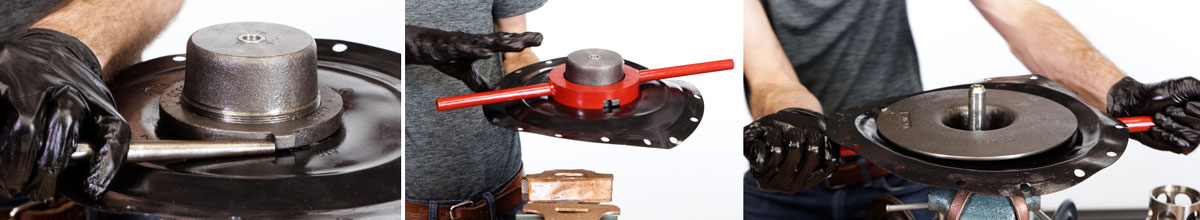
- It’s also good to inspect the part of the diaphragm under the diaphragm nut. If you don’t have the tool, you can flip the diaphragm assembly over and remove the diaphragm nut, using a hammer and punch.
- Put the Kimray Diaphragm Nut Tool on the diaphragm nut. Then put the diaphragm plate into the vise. After removing the nut, you can inspect the diaphragm fully and replace it if needed. It is not included in the repair kit. If it is damaged, you will need to order a replacement.
How to Inspect and Clean a Cage Guided High Pressure Control Valve
Before assembling the valve, you need to inspect a few of the key components that are often affected due to the severe impact of particles that flow through the valve. If any of these parts are damaged, you will need to order a replacement.
- Verify that the cage has not lost its shape.
- Next, inspect the piston for signs of corrosion on the outside surface.
- Also check for scoring or scratches on the inside of the seat.
- If the ratio plug has scratches, corrosion or wear, it will need to be replaced.
- Lastly, inspect all threads for nicks, burrs and flats. A thread repair tool may be used for light damage.
If there are multiple components that are worn and will need to be replaced, you may consider ordering a complete plug assembly. This will save you time and money, making the repair much easier. Complete plug assemblies are listed on the tech specs page. See our video about trim set options for more details.
How to Assemble a Cage Guided High Pressure Control Valve
Diaphragm Assembly
- To begin assembly, thread the diaphragm over the diaphragm plate. The bowl of the diaphragm should always face the diaphragm plate.
- Then add grease to the lower threads of the diaphragm plate.
- Thread the diaphragm nut on by hand.
- Place the diaphragm nut tool on the diaphragm nut. Flip it over and place the diaphragm plate in a vise with brass jaws to fully tighten.
Plug Assembly
- With the two flats of the piston in the vise with brass jaws, install the O-Ring (4086) and lightly apply grease.
- Mount the seat disc on top of the piston with the beveled side facing up.
- Insert the ratio plug bolt through the ratio plug and install the O-Ring (4773) around the bolt.
- Apply Loctite to the threads and tighten it with a 5/8” socket to until it comes to a complete stop.
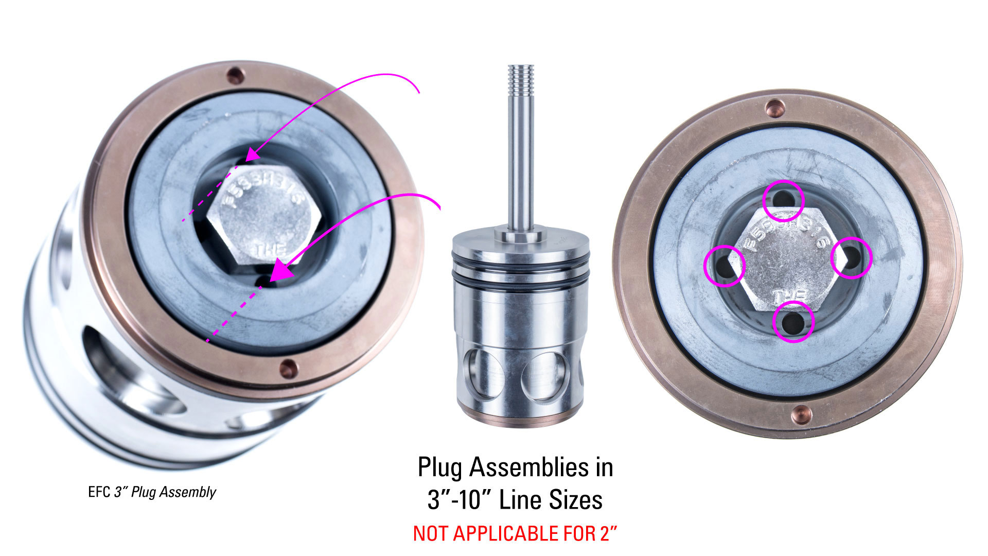
In all models except the 2” line size, you will need to align the holes in the piston and ratio plug.
- Remove the piston assembly from the vise and replace it with the valve body.
- Next, Install both O-rings (4768) on the outside of the cage.
- Then install the back up (4771T), quad ring (4769Q) and second back up (4771T) into the cage.
- Add grease to the two backups and quad ring inside the cage.
- Insert the piston assembly into the cage.
- Install the seal ring (6468P) onto the seat.
- Thread the seat onto the cage assembly and use the Kimray seat tool to fully tighten it.
- Apply grease to the bottom of the seat so that the (2099) O-ring stays in place.
- Also grease the two O-rings on the outside of the cage.
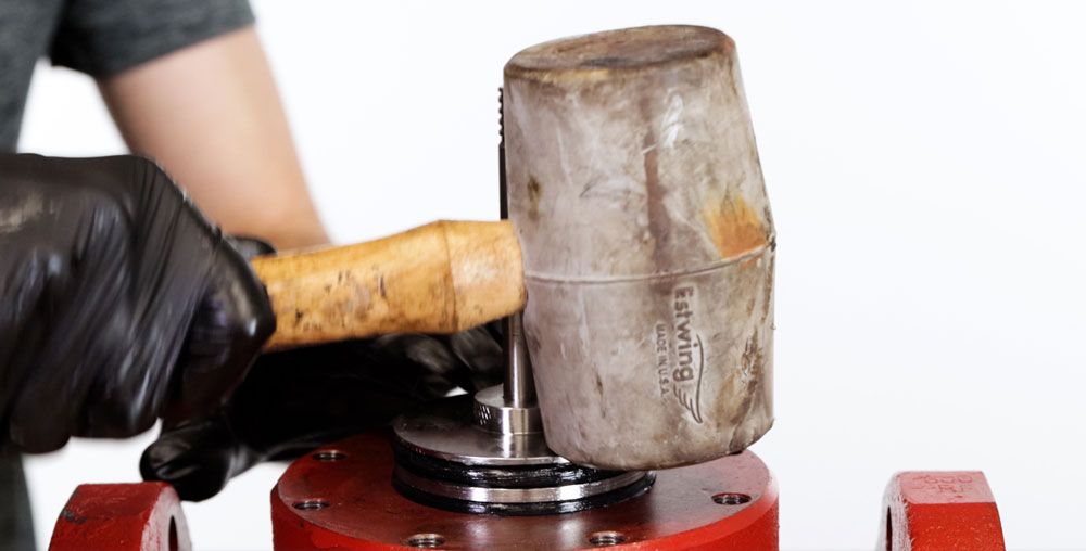
- Put the entire assembly into the valve body and use a mallet to tap it into place. Do not strike the stem, only the top of the cage.
Upper Housing
- Mount the upper housing to the body, facing the safety relief hole on the same side as the tapped holes on the body.
- Tighten the bolts to 25-30 ft-lbs. in a crisscross pattern to avoid any misalignment. Do not overtighten.
Stuffing Box
- Insert the new felt wiper (527) followed by the retainer washer and new snap ring (940).
- Put the new O-ring (520) on the outside of the stuffing box.
- Slide the (533) packing rings over the (534) packing sleeve.
- Coat the inside of the stuffing box with grease and push the packing sleeve into the assembly.
- Next, put in the packing follower.
- Fill the stuffing box with grease then insert the spring.
- Also add grease to the outer O-ring, being careful not to grease the threads.
- If your stuffing box is stainless steel (S6 in the product code), use anti-seize on the threads of the stuffing box to prevent galling or seizing. Otherwise, make sure the threads are clean.
- Thread the assembly back onto the upper housing. Use an adjustable wrench on the flats to fully tighten in place. Do not use a pipe wrench on the stuffing box and do not overtighten.
Lower Adjusting Screw & Yoke
- Place a new O-ring (537) on the outside of the adjusting screw
- Then install a new O-ring (530) inside.
- Insert a new felt wiper (527).
- Followed by the retainer washer.
- Use snap ring pliers to attach the new snap ring (940).
- Apply grease to the outer O-ring.
- Install it into the yoke with a 1-3/8” socket and extension.
How to Assemble for Fail Open or Fail Close
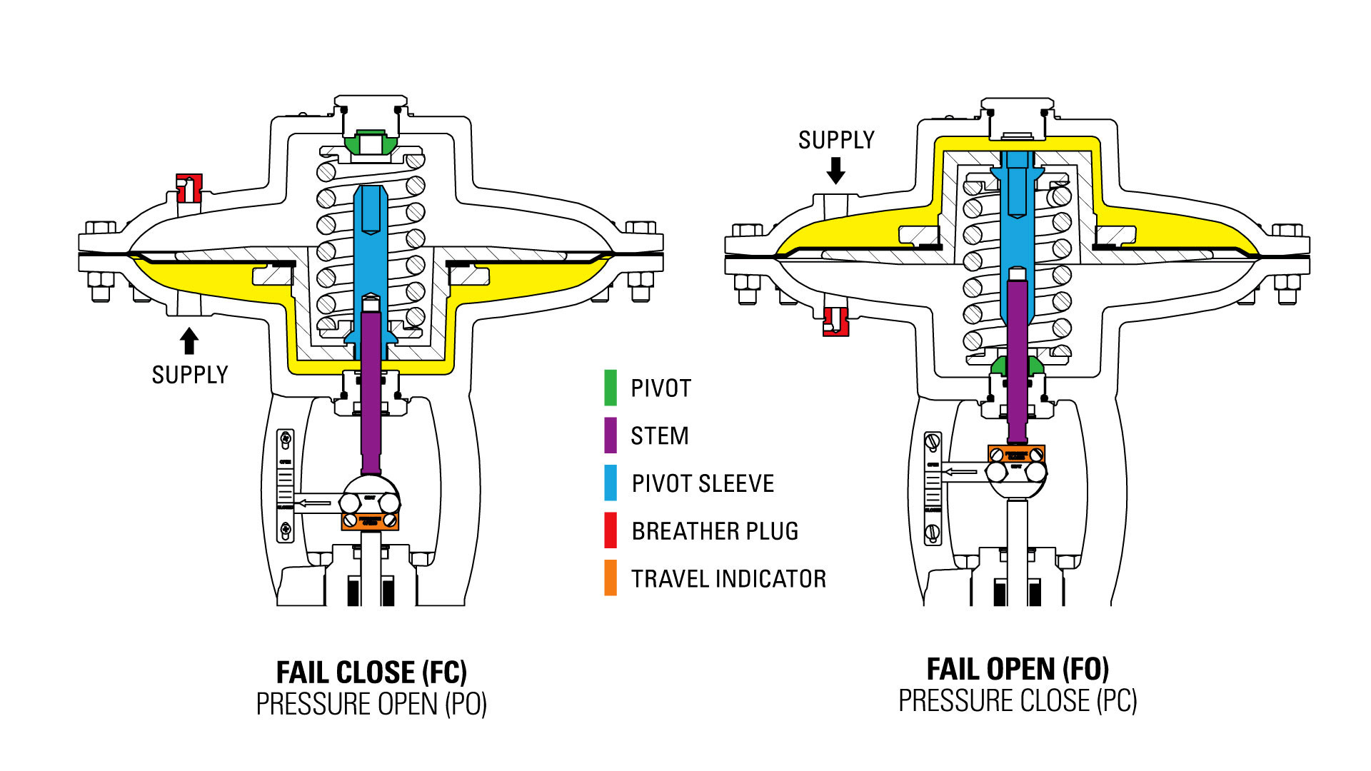
Now you have the option to assemble for fail open (pressure close) or fail close (pressure open) operation.
Assembly for Fail Open (Pressure Close / PC)
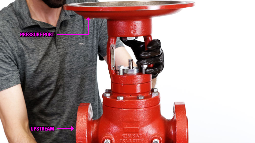
- To assemble for fail open operation, first mount the yoke on the valve body and fully tighten the four bolts. Align the pressure port with the upstream side to keep the same original orientation.
- Apply Loctite to the threads of the upper stem and insert it into the pivot sleeve with a 3/8” wrench.
- Add a dob of grease inside the yoke assembly, enough to block the hole in the bottom.
- Add oil inside the yoke to fully cover the lower adjusting screw.
- Install the pivot on the lower adjusting screw with the bevel side facing up.
- Install the lower spring plate, spring and upper spring plate.
- Grease the upper spring plate.
- Install the diaphragm assembly, pushing the stem through the lower adjusting screw.
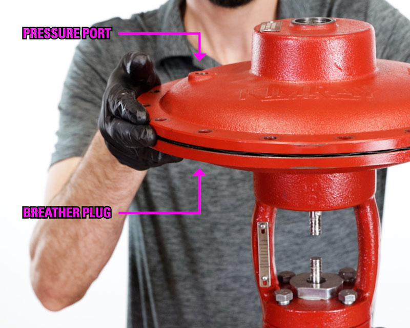
- Replace the bonnet, aligning the pressure port and breather plug hole.
- Install the bolts and lifting rings using a 9/16” and 11/16” wrench and tighten to 25-30 ft-lbs. Use a crisscross pattern and do not overtighten.
- Place the (537) O-ring on the upper adjustment screw.
- Add grease around the O-ring and thread it into the bonnet with an adjustable wrench.
- Install the breather plug into the bottom pressure port, so that the hole faces the bonnet.
- Apply 30 psi of supply pressure to lower the stem.
- Attach the indicator tag and travel indicator onto the coupling block with the flats on top. Use a 7/16” socket to tighten the bolts.
You can now remove the supply pressure, and your repair is complete
Assembly for Fail Close (Pressure Open / PO)
- For a fail close orientation, first mount the yoke on the valve body and only hand start the four bolts. This will make it easier to align the upper and lower stem later when attaching the coupling block.
- Align the pressure port with the upstream side to keep with the same original orientation.
- Apply primer and Loctite to the threads of the upper stem.
- Insert it into the pivot sleeve on the flat side of the diaphragm plate.
- Use a 3/8” wrench on the stem flats to tighten it to the diaphragm plate.
- Add a dab of grease inside the yoke assembly, enough to block the hole in the bottom.
- Add oil inside the yoke to fully cover the lower adjusting screw.
- Take the diaphragm assembly and push the stem through the lower adjusting screw.
- Grease the bottom of the pivot sleeve
- Then install the lower spring plate, spring, and upper spring plate.
- Add grease to the top of the upper spring plate.
- Replace the bonnet, aligning the pressure port and breather plug hole.
- Install the bolts and lifting rings using a 9/16” and 11/16” wrench and tighten to 25-30 ft-lbs. Use a crisscross pattern and do not overtighten.
- Make sure the spring plate is aligned.
- Place the (537) O-ring on the upper adjustment screw.
- Add grease around the O-ring and in the divot of the pivot.
- Place the pivot on the screw and thread it into the bonnet with an adjustable wrench. Do not fully tighten it yet to make it easier to attach the coupling block.
- Attach the indicator tag and travel indicator onto the coupling block with the flats on top. Use a 7/16” socket to tighten the bolts.
- Now you can fully tighten the 4 housing bolts.
- Install the breather plug on the top of the bonnet, so the breather hole faces the bonnet.
- Now fully tighten the adjusting screw.
That completes our repair. If you have any questions about this process or the custom Kimray tools used, contact your local Kimray store or authorized distributor.