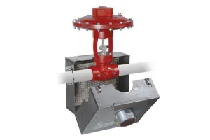
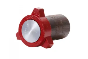
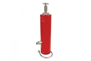
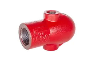
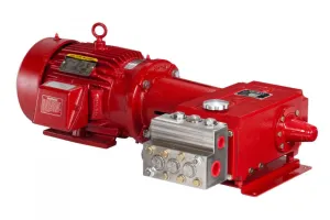
Many upstream energy producers are now using automated electric systems to run locations efficiently and with fewer manual adjustments required.
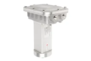
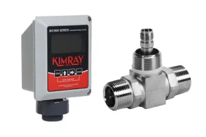
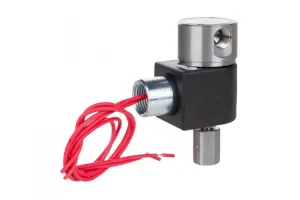
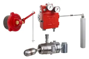
To support these systems, we have added a key product to our Kimray Electrix™ line: the Electric Level Sensor.
In this video I'm going to show you how to setup the Kimray Electric Level Sensor to operate with the Electric Pilot and Electric Actuator for precise level control.
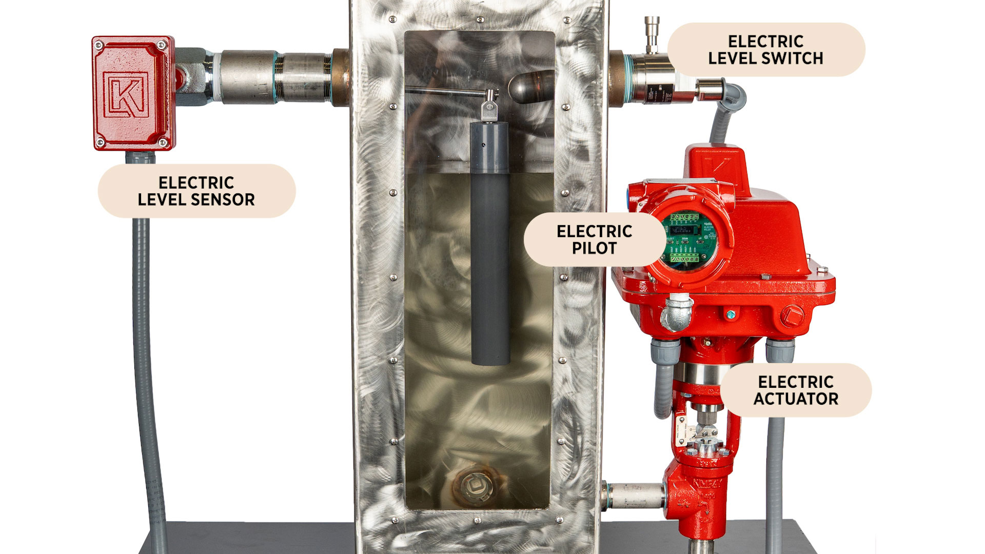
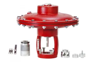
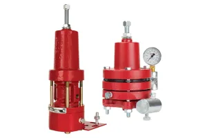
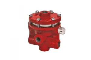
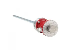
We have four products here that work in conjunction:
- Electric Level Sensor
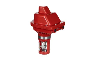
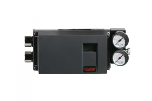
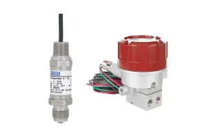
- Electric Pilot
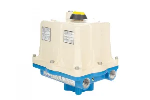
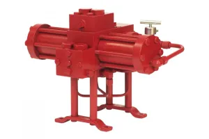
- Electric Actuator
- Electric Level Switch (as a high level shutdown)
Important Safety Notice
This video demonstrates general wiring and installation steps and is intended as a supplemental reference only. It does not replace the full Kimray IOM manual, which contains all required warnings, torque specs, wiring ratings, and hazardous-location requirements.
By following this information, you assume full responsibility for compliance with the manual and all applicable codes and regulations. Kimray assumes no liability for injury, equipment damage, or loss resulting from improper installation or use.
Before performing any work:
- Release all system pressure, de-energize and lock out the equipment, and use proper wiring methods and conduit seals rated for the location.
- Always wear appropriate PPE
- Follow all instructions, ratings, and specifications exactly as provided in the full Kimray IOM manual. Failure to do so may impair equipment protection and voids equipment ratings.
Wiring
Electric Level Sensor
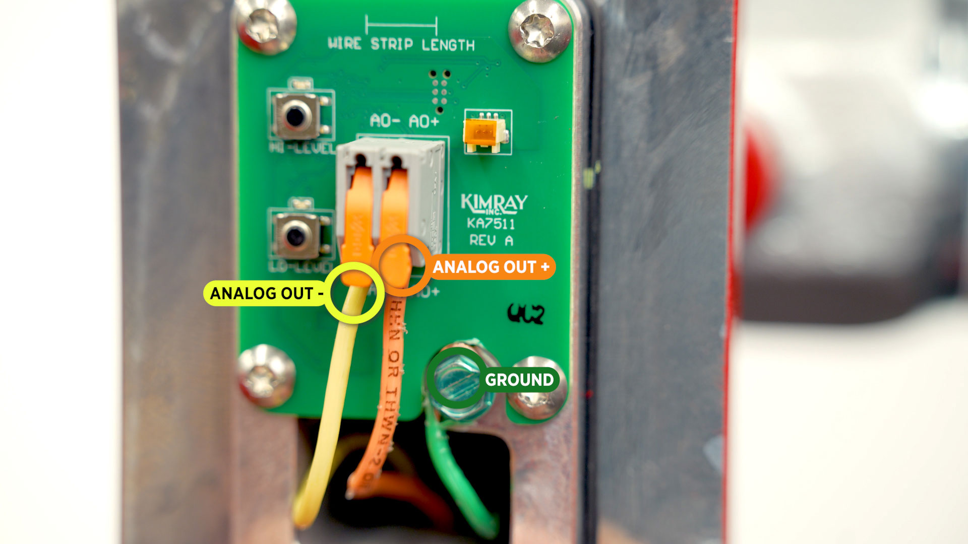
- Take off the sensor lid by removing the four 3/16” hex screws.
- Connect your ground wire
- Secure the analog out positive (AO+) and negative (AO-) wires.
Electric Pilot
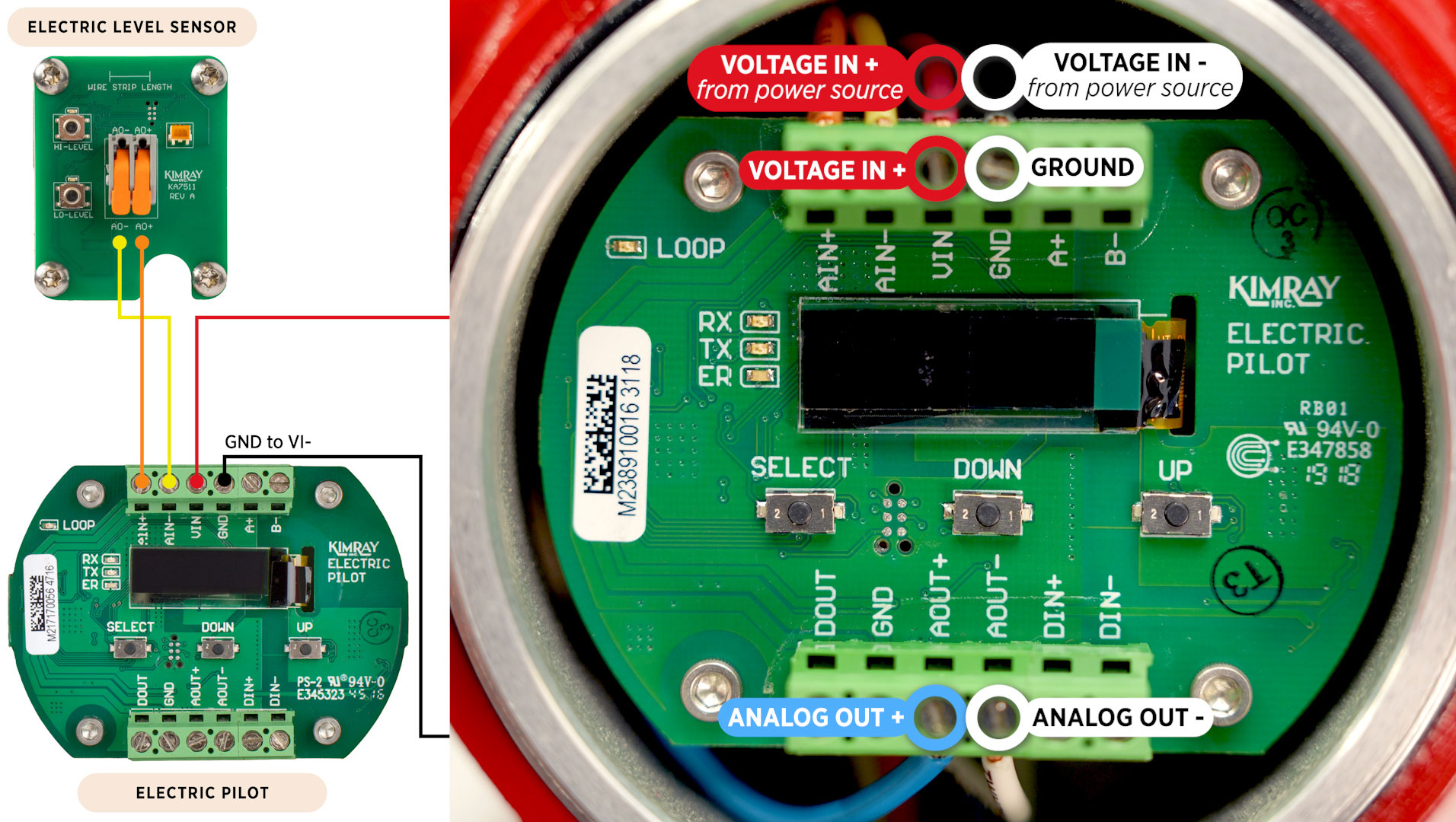
We'll be connecting the Electric Level Sensor to the Kimray Electric Pilot. You can think of the pilot as a one-input PLC. This sensor output could connect instead to a PLC or RTU.
- Connect the (AO+) from the sensor to the (AI+) on the Electric Pilot.
- Connect the (AO-) from the sensor to the (AI-) on the Electric Pilot.
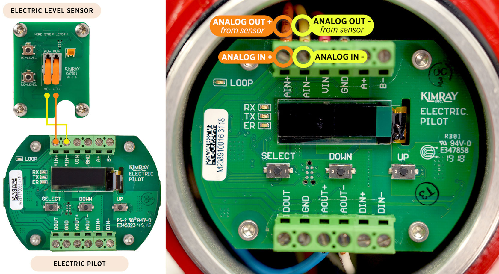
- Voltage In positive (VI+) will terminate into (VIN) on the pilot.
- Voltage In negative (VI-) will terminate into the ground terminal (GND) on the pilot.
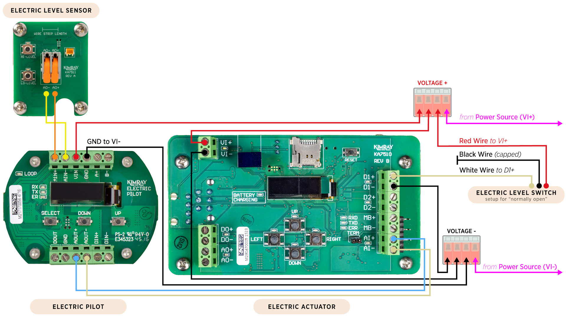
- The Analog Out positive (AO+) and Analog Out negative (AO-) will run to the Analog Input positive (AO+) and Analog Input negative (AO-) on the Electric Actuator.
Electric Level Switch
For this setup, we also have an Electric Level Switch used as a high-level shutdown. There are 3 wires coming from the switch: white, red, and black. This setup is for “normally-open” operation.
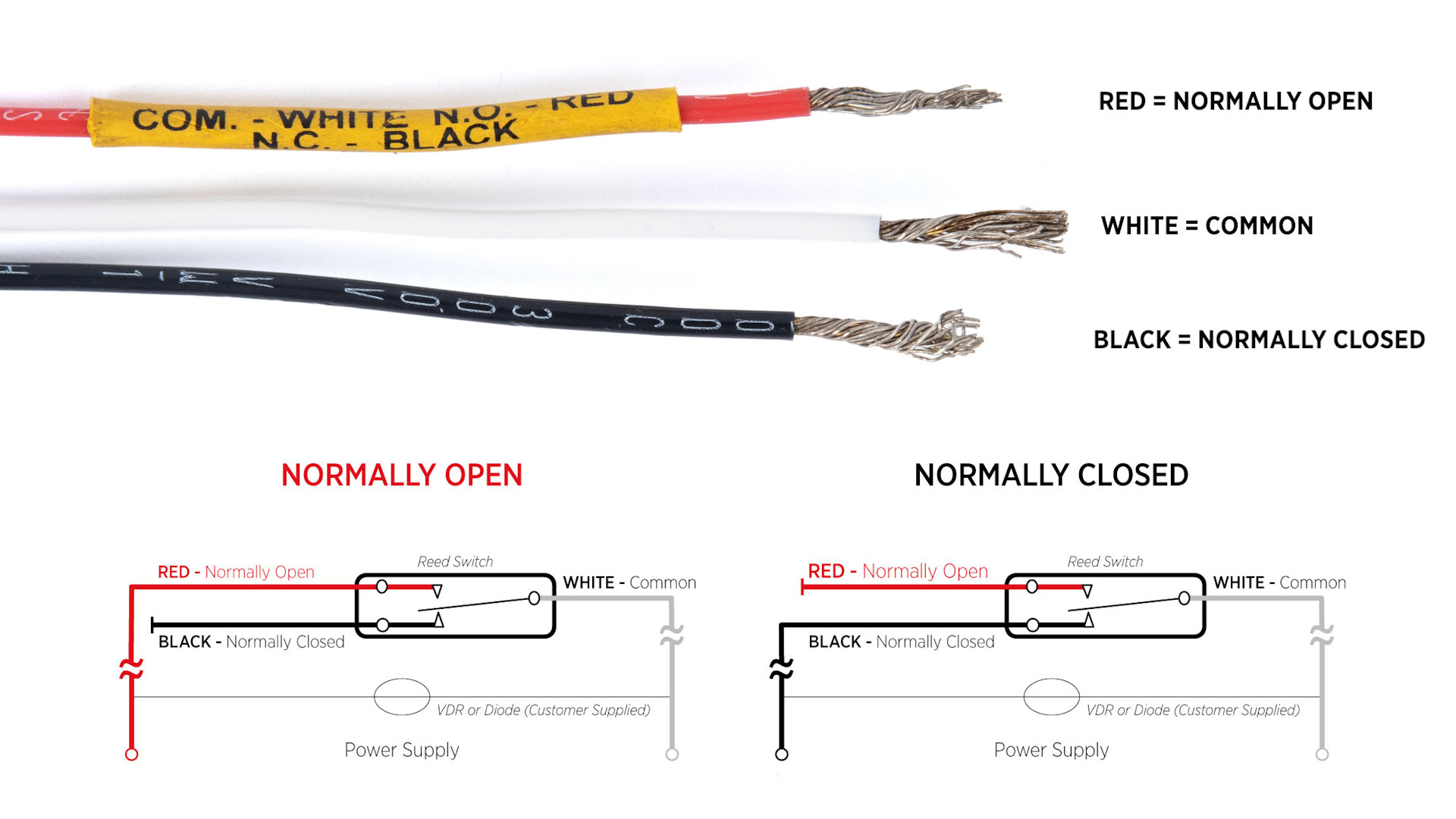
- The white wire is connected to the actuator at D1+.
- The red wire from the switch is wired into the shared power WAGO connector.
- The black wire is capped.
- The D1- wire is connected to the negative side of the power loop.
For more information about setting up an Electric Level Switch, see our other video on that topic.
Connecting Voltage
Now we're going to connect voltage into the actuator board. These power wires are connected to the loop.
- Voltage in + and – coming from the power source are connected in that loop to all other devices.
View Wiring Diagram Illustration
With wiring complete, you can now turn on your power.
Electric Actuator Calibration
Now it's time to calibrate these components.
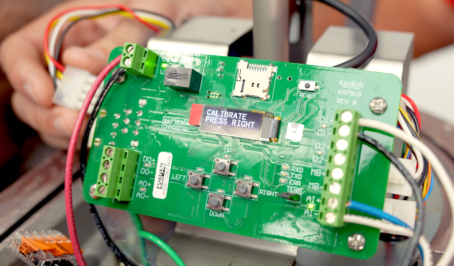
- Plug in your backup battery on the Electric Actuator. The screen on the actuator should now say calibrate press right.
- To calibrate, simply press the RIGHT button, and it will calibrate itself in about 20 seconds.
Electric Pilot Programming
We’ll spend most of our time programming and calibrating here at the Electric Pilot. A helpful metaphor for these components is the eye, the brain, and the hand.
The sensor functions like an eye—it watches your process. The pilot is the brain—it decides what should happen. The actuator and valve are the hands—they carry that decision out. And then the eyes watch again, and the loop continues.
So when we program the pilot, we are working directly with the brain of this operation.
- Sensor Type–
The pilot should say “sensor type Undefined”. Push UP or DOWN to get to LEVEL, then press SELECT. - Units of Measurement–
The next screen will ask for the unit of measurement. We’ll select Inches and then press SELECT. - Sensor Max–
Next, we’ll set the sensor maximum, which will be the 20mA output. Because we have a 12” displacer, we’ll select 12 and press SELECT. That will set it so 20mA is the output when the displacer is entirely submerged. - Sensor Min–
The sensor minimum is where the 4mA output will be, which will be set to zero. - Application–
Now we will define the application. For this set up, we want GAP CONTROL. This is the most frequently used application because it can control a gap as wide as your displacer or down to a very small gap to accommodate your control needs. - Open At (High Side)–
We will set the high side of our gap control to 10”. This could be anything within the min and max of the displacer. - Close At (Low Side)–
The low side of the gap control tells the valve when to close. We’ll set this to 1in, then press SELECT. - RUN Mode–
Now use the UP or DOWN buttons to get to RUN mode. Press SELECT.
Now we can see several things on the home screen.
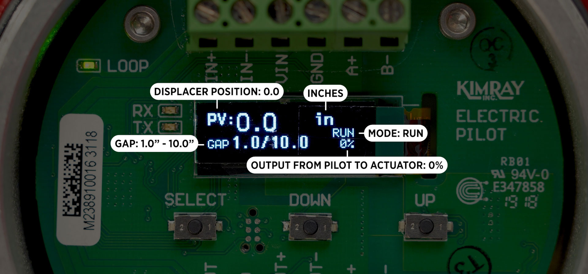
- We are controlling from 1-10".
- The PV is the position of the displacer and it’s reading 0 because we have no liquid on it.
- We are reading in inches.
- Our output from the pilot to the actuator is 0.
- And the pilot is in Run Mode.
The Electric Level Sensor comes factory calibrated for top level control. If this is your application, this completes the process. You can now turn on your flow and confirm everything is working correctly.
Electric Level Sensor Calibration
If you’re setting up for interface control, you will now need to calibrate your electric level sensor for interface.
“Seeing” the Displacer in the vessel:
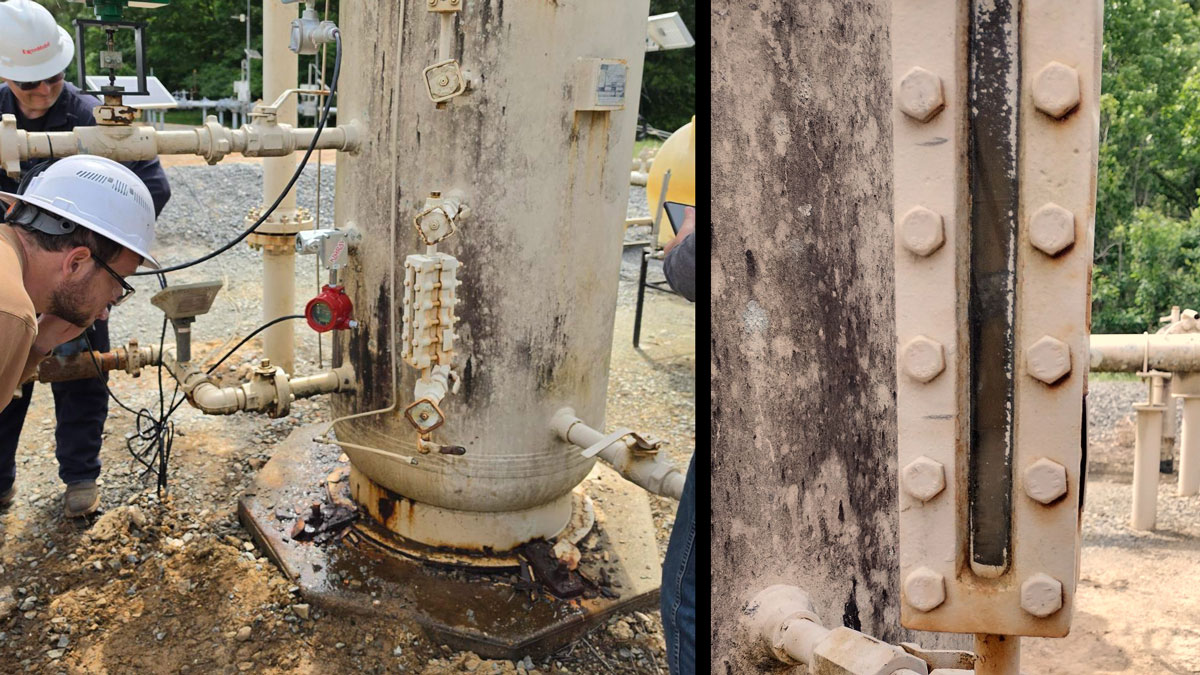
It’s easy to see where our displacer is on this demo unit, but in a real-life scenario there are a couple ways you could do this accurately. You could use a sight glass, but it’s not always the most reliable.
The most precise way is to use the readout on the Electric Pilot or your PLC.
• 4mA = level is below the displacer
• 20mA = level is above the displacer
To see the true position of the liquid level on the pilot, go to ADVANCED SETTINGS, then CALIBRATE SENSOR IN to see the level sensor output. As the arm moves, the readout changes. There’s a small amount of dead band, so +/- a few tenths of a mA is normal, so it may hold around 19.8.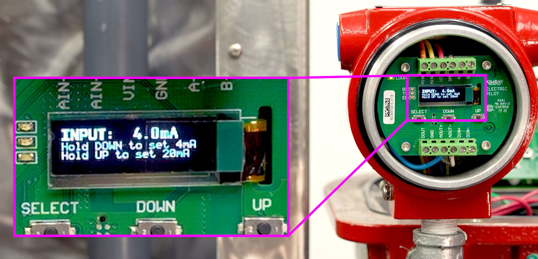
- First, turn the pilot back to off mode. To quickly get back to the home screen, hold select for 3 seconds.
- HI-LEVEL –
- Hold down the HI-LEVEL button on the sensor for 5 seconds. Once the LED begins to flash, release the button. While the light is on, increase the liquid level in your vessel until you can confirm that it is above the displacer.Once the level is above your displacer, shut off the incoming flow to the vessel to maintain the liquid level until calibration is complete.
- Now press the HI-LEVEL button. It will take 45-60 seconds to run the calculation.
- LO-LEVEL –
- Once completed, the LO-LEVEL LED will begin to blink.
- Now empty your vessel liquid until the water level is below the displacer.
- Once the liquid level is below the displacer, close the downstream flow to maintain liquid level until calibration is complete.
- Press the LO-LEVEL button. It may take up to 60 seconds to run the calculation again.
- Once finished, both LEDs will flash 5 times to indicate that calibration is complete.
You can now turn on your flow and confirm everything is working correctly.
Factory Reset
If you ever need to get back to factory settings on the electric level sensor:
- Hold the LO-LEVEL button for 5 seconds until the LED starts flashing.
- Then hold the LO-LEVEL button again for 5 seconds until both LEDs turn solid.
Let go, and now it is factory reset.
Left Mount vs Right Mount
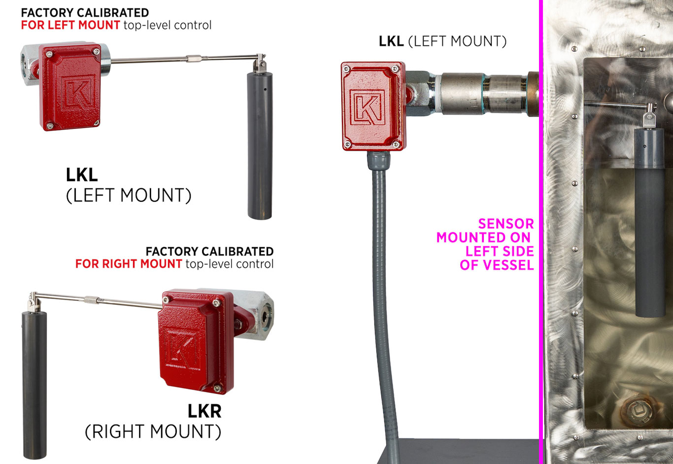
The Electric Level Sensor is available to order for left or right mount and each one factory calibrated for the intended setup. A left mount means that when facing the sensor, it is mounted on the left side of the vessel.
However, it is also field reversible, and the orientation can be swapped, for example, if the wrong one was ordered, or a setup changes. An important note about this is that you will need to calibrate the unit after reversing the mount, and every time the unit is factory reset.
Contact Kimray Support with any questions about the Kimray Electric Level Sensor or any other Kimray Electrix™ product.