

Over time, all oil and gas wells lose flow volume.
When this happens, you may find that your valves will start to let too much production through and then overcorrect, leading to chattering or slamming.
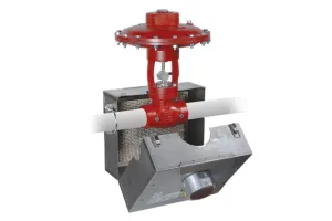
In larger 3” or 6” valves, this slamming can be very forceful, damaging the products and piping.
Inconsistent flow, chattering, and hammering are a few common symptoms of an oversized valve for your flow volume, especially with pressure regulators.
Can I Convert an Existing Valve that is Oversized?
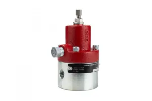
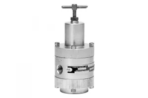
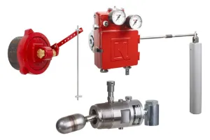
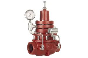
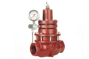
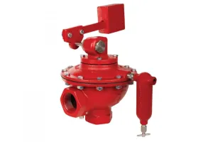
The good news is that there is a solution to this issue that doesn’t require purchasing a new regulator or even changing the size of your pipes: converting pressure regulators from full port to reduced port.
Standard regulators are configured as full port, but you can convert them to reduced port—effectively changing the inner valve size—without replacing the valve or piping or taking the product out of line.
What do you need?
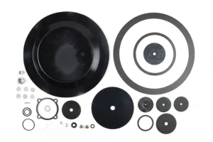
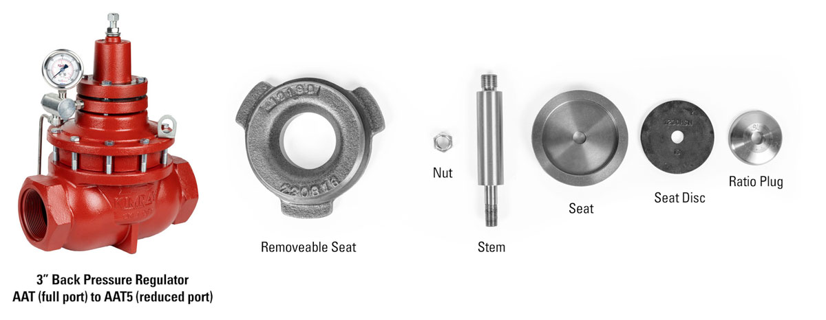
To find what components you need, open the technical specifications for your product on kimray.com. Using the parts list table, compare your valve size with each of the six items that have “standard” and “reduced” options.
This chart below shows the components needed as well as the repair kits and tools to complete the job safely and easily. Special tools codes can also be found in the Installation Operation & Maintenance Guide on each product page.
Ductile Regulator Configurations
| End Connection | 1” | 2” | 3” | 4” | 6” |
|---|---|---|---|---|---|
| Product Codes Full → Reduced | AKB → AKB5 | AAR → AAR5 | AAT → AAT5 | AAW → AAW5 | AAY → AAY5 |
| Removeable Seat* | - | 4934 | 1219D | 1220D | 1221 |
| Valve Stem | - | - | 1222SS6 | 1223SS6 | 1224SS6 |
| Ratio Plug | 4932 | 4933 | 1228SS6 | 177SS6 | 178 |
| Seat Disc | - | - | 1229 | 159 | 160 |
| Seat | - | - | 1230HSN | 164HSN | 165HSN |
| Nut | - | - | 173 | 173 | 906 |
| Repair Kit | RYD | RYG | RYK | RYO | RYR |
| Removeable Seat Tool (Full Port) | - | Socket: 6945SW Handle: 272SW | Socket: 6946SW Handle: 273SW | Socket: 6947SW Handle: 274SW | Socket: 6948SW Handle: 275SW |
| Removeable Seat Tool (Reduced Port) | - | 4943SW | 1219SW | 1220SW | 1221SW |
| Stem Guide | - | 1852 | 1853 | 1854 | 1855 |
* Part numbers include a preinstalled gasket on the Removeable Seat.
Steel Regulator Configurations
| End Connection | 1” | 2” | 3” | 4” | 6” |
|---|---|---|---|---|---|
| Product Codes Full → Reduced | AKC → AKC5 | AGB → AGB5 | AGC → AGC5 | AGD → AGD5 | AGE → AGE5 |
| Removeable Seat* | 4934SS6 | 1219SS6 | 1220SS | 1221SS6 | |
| Valve Stem | 1222SS6 | 1223SS6 | 1224SS6 | ||
| Ratio Plug | 4932 | 4933 | 1228SS6 | 177SS6 | 178 |
| Seat Disc | 2585SS6 | 2493SS6 | 2494SS6 | ||
| Seat | 1230HSN | 164HSN | 165HSN | ||
| Nut | 173 | 173 | 906 | ||
| Repair Kit | RYD | RYGS6 | RYKS6 | RYOS6 | RYRS6 |
| Removeable Seat Tool (Full Port) | Socket: 6945SW Handle: 272SW | Socket: 6946SW Handle: 273SW | Socket: 6947SW Handle: 274SW | Socket: 6948SW Handle: 275SW | |
| Removeable Seat Tool (Reduced Port) | 4943SW | 1219HTSW | 1220HTSW | 1221HTSW | |
| Stem Guide | 1852 | 1853 | 1854 | 1855 |
* Part numbers include a preinstalled gasket on the Removeable Seat.
How to convert a regulator from full port to reduced port
In this video, first we’ll show a 3” regulator conversion process with six components. Then, we’ll show the process with a 2” regulator, which only requires two parts to be swapped.
If your product has been in service, we highly recommend installing a repair kit during this process, which we cover in these videos:
Watch: How to Repair a Back Pressure Regulator
Watch: How to Repair a Pressure Reducing Regulator
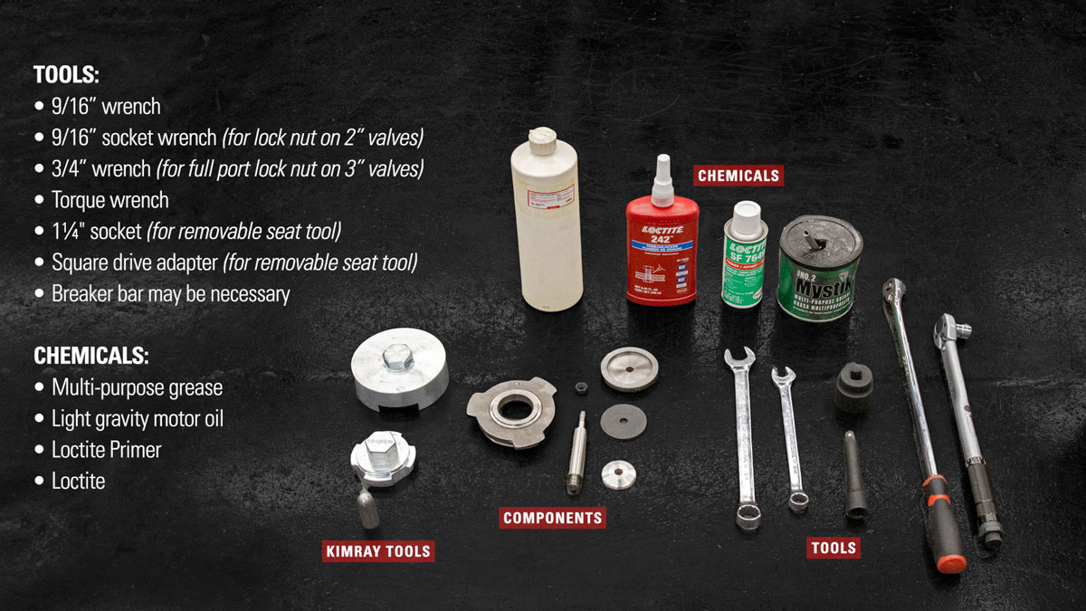
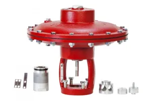
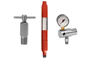
For this conversion, you will also need the following:
Tools
- 9/16” wrench
- 9/16” socket wrench (for lock nut on 2” valves)
- 3/4” wrench (for full port lock nut on 3” valves)
- Torque wrench
- 1¼" socket (for removable seat tool)
- Square drive adapter (for removable seat tool)
- Breaker bar
Chemicals
- Multi-purpose lubricant/grease
- Any kind of light gravity motor oil
- Loctite
- Loctite Primer
WARNING: Before any service, be certain that the valve is fully isolated and that all pressure upstream and downstream has been relieved. Use bypass valves or fully shut off the process. Be sure that any operating or instrument gas lines have been disconnected. Never assume that a check valve is fully blocking the downstream line. Never tighten any fitting or the main connections to the regulator while there is pressure on the line.
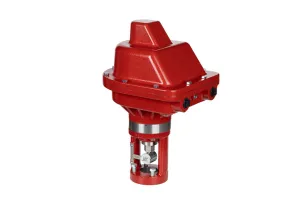
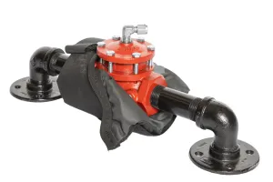
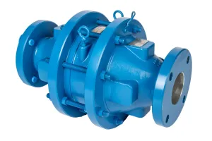
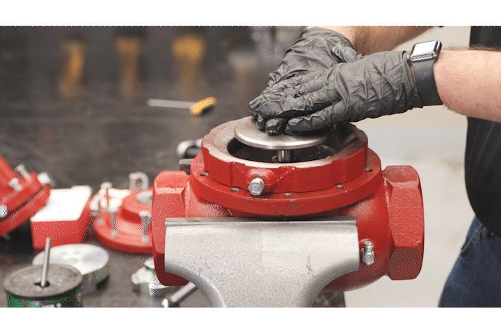
3” AAT Disassembly
Before you begin, it can be helpful to mark a line down each section of your regulator so that during assembly, the markings can be easily aligned back in the same orientation.
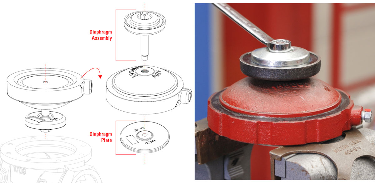
Pilot Housing / Bonnet
- Position the regulator in the vise so you can access the tubing.
- Start by loosening the adjusting screw until spring tension has been released.
- Use a 9/16” wrench to loosen the tubing connectors.
- Unthread the four bonnet bolts with a 9/16” wrench and rotate the pilot housing to remove the tubing. Save the tubing for re-assembly.
- Remove the bonnet and pilot housing, keeping the assembly together. Prop the assembly upright to protect the pilot plug.
Upper Housing
- Use a 9/16” wrench to remove the upper housing bolts, then remove the upper housing from the body.
Lower Housing
Disassembly
- Set the diaphragm aside.
- Remove the lower housing. You may need a flathead screwdriver or similar tool to separate it from the body. Be careful not to damage the gasket when prying the pieces apart.
- Carefully discard the oil from inside the lower housing.
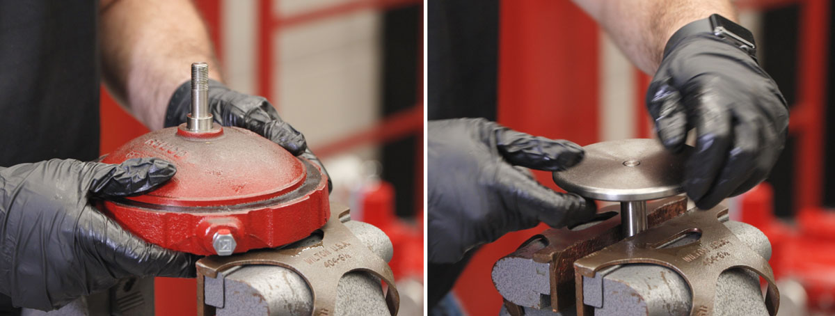
- Put the diaphragm plate of the lower housing into a vise.
- Use a 3/4” wrench to remove the lock nut.
- You’ll need to separate the diaphragm plate from the assembly, but this could happen in one of two ways.
Scenario 1: While you’re removing the lock nut, the stem may unthread from the diaphragm plate. This is ideal because this entire assembly will be replaced.
Scenario 2: If your lock nut unthreads from the stem, remove the ratio plug, seat, seat disc, and lower housing. Flip the assembly over, putting the stem in the vise to unthread the diaphragm plate by hand. Use soft jaws to not damage the stem.
- The ratio plug, seat and seat disc can be repurposed for other projects if they show no sign of wear.
Assembly
- Put the new stem into the vise, short end up. Use soft jaws to not damage the stem.
- Apply primer and Blue Loctite® to the short end of the new valve stem.
- Hand thread the diaphragm plate onto the stem.
- Now flip the assembly and put the diaphragm plate into the vise.
- Add grease to the O-rings and backups inside the lower housing.
- To prevent shearing the O-ring inside the lower housing, use a stem guide placed on the stem.
- Slide the lower housing over it. Then remove the stem guide.
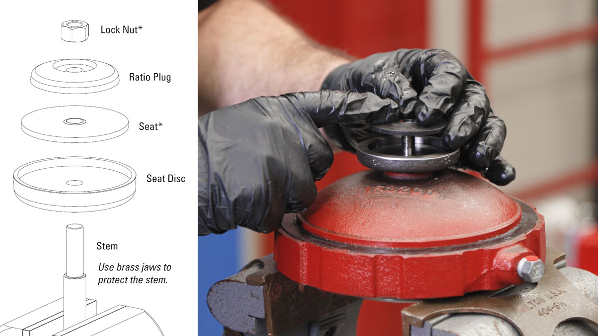
- Place the new seat disc (1229), seat (1230HSN) and ratio plug (1228SS6) on top of the stem.
- Apply all-purpose grease to the threads of the stem.
- Hand-start the new lock nut (173) threads.
- Hold the seat disc with one hand and use a 9/16” socket to tighten the lock nut. DO NOT OVERTIGHTEN because it can deform the seat. Tighten it to the point where the seat disc no longer rotates.
- The gasket should be on the lower housing shoulder. This is part of the repair kit procedure, but for the conversion, double check that this is still in place and properly greased on both sides.
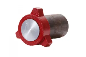
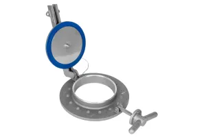
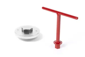
Removeable Seat
Disassembly
- Use the Kimray seat removal tool combined with a 1 and ¼" socket and socket extension to take out the removable seat. A breaker bar can help to get enough leverage to remove the seat from the body.
This removeable seat is an extra piece that you can save and reuse for other projects if desired if it shows no signs of damage.
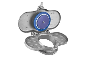
Assembly
- Apply grease to both sides of the gasket on the new removeable seat. All gaskets put into the valve assembly must be lubricated with a multi-purpose grease.
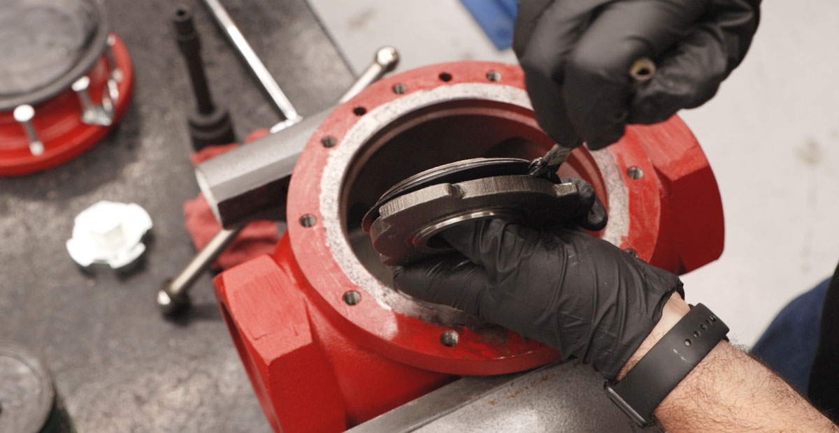
- Install the removable seat with gasket into the body with the seat tool and torque to the recommended torque specification. Do not overtighten the seat, which could damage the gasket.
| Size/Seat | Torque |
|---|---|
| 2” Valves | 30 FT-LB |
| 3” Valves | 80 FT-LB |
| 4” Valves | 80 FT-LB |
| 6” Valves | 300 FT-LB |
Lower Housing Assembly
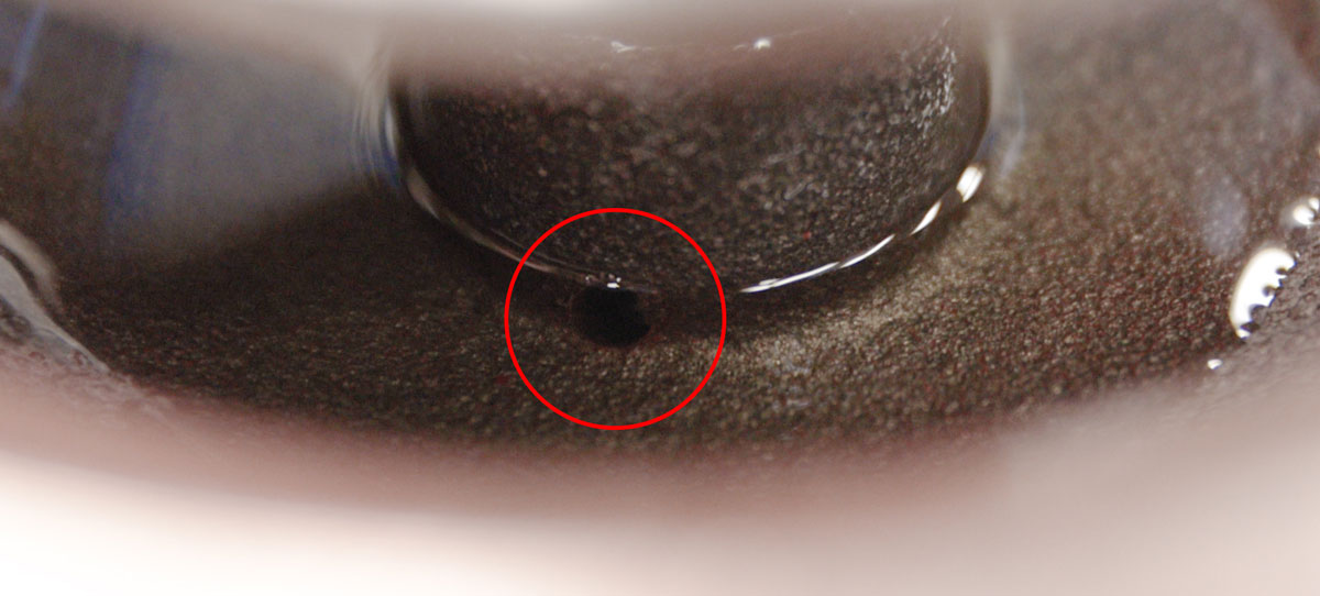
- Install the lower housing into the body. The breather plug should face the same directions as the fittings and be between the inlets of the body, clocked just off centered.
- Fill the lower housing with all-purpose oil until the communication hole to the lower stem is fully submerged.
- Being careful not to pinch your fingers, push down the diaphragm plate directly on top.
- Install the main diaphragm onto the lower housing assembly, making sure it is placed in a “bowl” position inside the lower housing.
- Place the upper housing on top of the lower housing, aligning the breather plug to be between the outlet holes in the body.
- Hand-tighten the bolts using the torque star pattern.
- Now fully tighten the bolts in a star pattern to avoid any misalignment. For 2”, 3” and 4” regulators tighten bolts to 25-30 FT-LB torque.
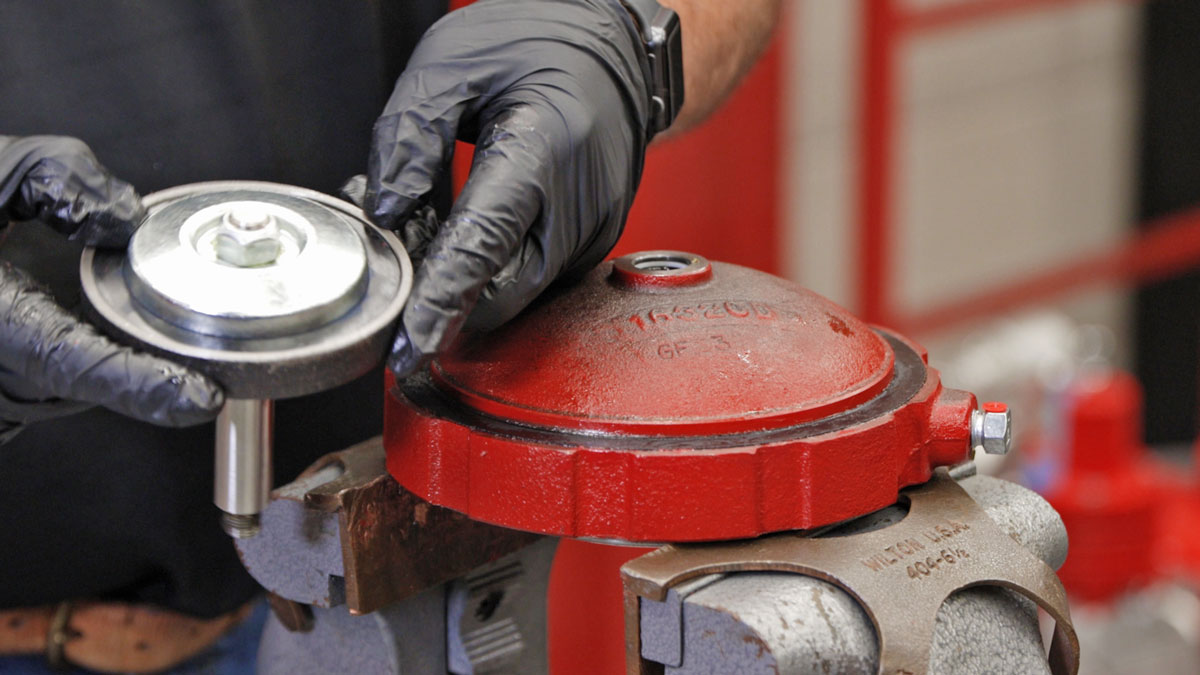
Pilot Housing / Bonnet Assembly
- Next, mount the pilot housing and bonnet assembly onto the upper housing.
- Hand-start the bolts but do not tighten them all the way.
- Install the tubing, but do not fully tighten the tubing fittings.
- Now fully tighten the bolds in a star pattern to avoid any misalignment. For 2”, 3” and 4” tighten bolts to 25-30 FT-LB torque.
- Once the bonnet bolts are tight, tighten the tubing fittings.
- Now your regulator is configured with a reduced port inner valve size and the adjusting screw can be tightened to your desired set point.

2” AAR DISASSEMBLY
For 2” regulators, the conversion is similar but with only two new components: the ratio plug and removeable seat.
- Begin the same way by removing the bonnet and pilot housing assembly, upper housing, and lower housing.
Ratio Plug
- Put the diaphragm plate into a vise.
- Use a 9/16” wrench to remove the lock nut.
- Remove the ratio plug and replace it with the new ratio plug (4933).
- Apply all-purpose grease to the threads of the stem and hand-start the lock nut.
- Hold the seat disc with one hand and use a socket to tighten the lock nut. DO NOT OVERTIGHTEN because it can deform the seat. Tighten it to the point where the seat disc no longer rotates.
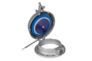
Removeable Seat
- Use the Kimray seat removal tool combined with a 1¼" socket and square drive adapter to take out the removable seat. A breaker bar may be necessary to get enough leverage to remove the seat from the body.
- Apply grease to both sides of the gasket on the new removeable seat. All gaskets put into the valve assembly must be lubricated with a multi-purpose grease.
- Install the removable seat with gasket into the body with the seat tool and torque to 30 FT-LB. Do not overtighten the seat, which could damage the gasket.
Assembly
- Re-assemble the valve as previously shown for the 3” model.
- Now your regulator is configured with a reduced port inner valve size and the adjusting screw can be tightened to your desired set point.
For questions about this process, or any other challenges your production site is facing, contact Kimray’s Technical Support team.