In this guide we’ll walk you through everything there is to know about float operated controllers.
From the basics of how it works to step-by-step repairs and troubleshooting, you’ll gain a solid foundation of knowledge on how to operate and maintain Kimray’s float operated controllers.
Use the table of contents to skip to different sections of the learning path.
1. How to Troubleshoot your Gen 3 Liquid Level Controller
When a level control system is not operating the way it should, potential problems could result, like dumping water into the oil line or oil into the water line. There are several possible causes for these operational issues.
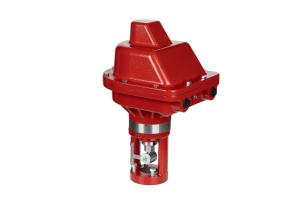
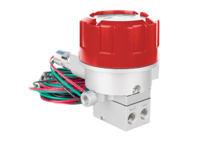
The main function of a level controller like the Gen 3 is to detect the liquid level inside a production vessel and communicate to the dump valve when to open or close, keeping the level at the desired point or within a specific range.
When the controller or valve is not operating properly, the symptoms can look the same for various root causes, so determining the cause of a problem can take some investigation.
Warning: Never tighten, loosen, or remove any fittings, lines or main connections while there is pressure on the line.
Problem 1: Liquid Level Over-Running the Displacer But Controller Not Actuating
When the liquid level reaches its set point, either at the top of the span or bottom of the span, the controller should actuate, meaning it sends an output signal or vents.
The controller should actuate somewhere along the length of the displacer. If the liquid level goes beyond the top of the displacer but the controller hasn’t actuated, or on the other end, if the liquid level drops below the bottom of the displacer and the controller has not actuated, this is a problem.
Here are 10 potential causes for the controller not actuating, and their solutions:
1. No Supply Gas Pressure
This first one may seem obvious, but it can happen, and that is, you might not have any pressure in your supply line. A good indicator of this is the supply pressure gage reading zero.
Check your supply source and make sure it is on and regulated to between 15 and 45 psi.
2. Level/Span Settings
The controller not actuating may just be a result of the level and/or span settings needing to be adjusted.
If liquid is overrunning the top, turn the spring adjustment knob counterclockwise to increase the spring tension to make the actuation happen at a lower level.
If liquid is dropping below the bottom of the displacer, turn the spring adjustment knob clockwise to decrease the spring tension to make the actuation happen at a higher level.
You may also need to reduce the span if you are in SNAP mode. this can be done by sliding the fulcrum towards the center of rotation of the torque lever. In Throttle mode, span setting would typically not be the issue, but as a rule of thumb, the position for the least amount of span in Throttle mode is the middle tick mark, but adjusting it inward or outward from the center tick mark could reduce the span depending on the application conditions.
3. Incorrect Setup—Direct / Indirect
For a Fail Closed Valve, the level controller should be set up in Direct Mode, and for a Fail Open Valve, Indirect Mode. If set up incorrectly, the controller will not actuate the way you want it to.
The switch from direct to indirect mode is easy. Just move the pilot lever from one side to the other. This chart, found in the installation operation and maintenance manual is an easy reference for which side the pilot lever should go when in Snap or in Throttle. For your convenience, this information is also given on the inside of the Gen 3 cover.
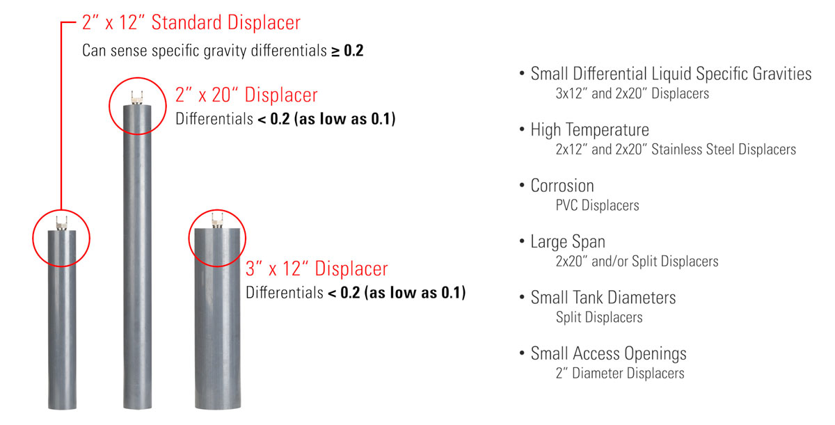
4. Undersized Displacer
If, by adjusting the spring tension and span settings, you’re still not able to alleviate this problem at both ends, this could be an indication that the displacer is undersized. When interfacing, if the specific gravity differential is below 0.2, buoyant force from displacer may not be sufficient to actuate the controller.
A larger Kimray displacer may be necessary. Over time, specific gravities in your system can change, which can account for a controller that was working fine, but then started to have these symptoms.
Switch to a larger displacer. Kimray’s standard displacer is designed to sense specific gravity differentials as low as 0.20. If you have a lower differential, Kimray offers larger displacers that can sense down to a 0.10 differential.
When switching out displacers, you may also need to change out the level adjusting spring, which brings us to our next potential cause.
1.1 Displacer Sizes
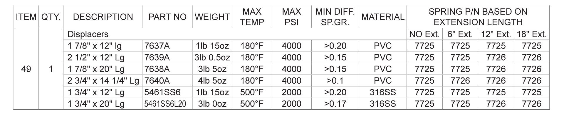
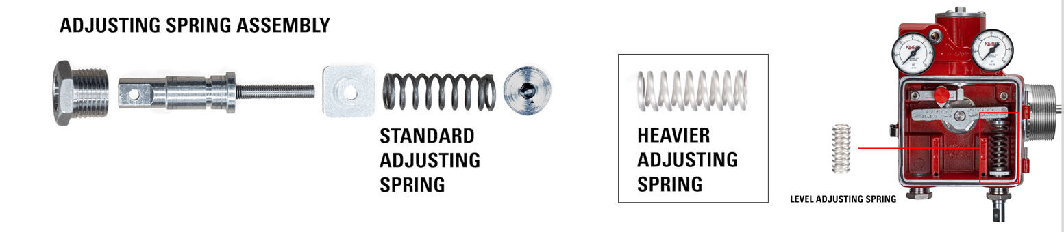
5. Wrong Size Level Adjustment Spring
Your displacer may be the right size, but you could have the wrong spring. Various combinations of displacer sizes and extension arm lengths could necessitate a heavier spring.
1.2 Spring Chart1.3 Adjusting Spring Assembly
This chart, located in the Gen 3 Technical Specifications document, specifies which spring you should use based on displacer size and extension arm lengths. There are only two springs that could be used, the standard and the heavy spring.
6. Contaminants Inside Pilot
Moisture or solids like sand, dirt or errant Teflon tape inside of the pilot or communication holes inside the casting could prevent the controller from actuating.
The supply gas should be clean and dry. The Gen 3 comes with a supply gas filter, but if this is not enough, we recommend installing an additional filter and/or drip pot or scrubber on the supply gas line.
The pilot plug inside allows for very precise control and low emissions, but contaminants can prevent the pilot plug from moving or restrict full range of motion. To check for contaminants, remove the pilot from the controller and disassemble. Check for any solids or moisture. Clean and dry the components before re-assembling.
7. Supply Line Blockage
Similarly, the supply line could be blocked due to moisture buildup. If there’s a dip or low spot in the line, water can collect and freeze, causing a complete blockage of supply air.
If you think this could be the issue, disconnect the lines and clean them out. Ensure there are no dips in the lines where moisture could collect and pool.
8. Downstream Pressure in Vent Line
If there is pressure downstream in the vent line due to a gas gathering system downstream, and that pressure is greater than the supply pressure, the level controller won’t vent.
Increase the supply pressure, but no more than 45 psi, or reduce the downstream pressure of the gas gathering system. Image of gas gathering system
9. Interference Inside Vessel
If there’s an obstruction inside the vessel not allowing full range of motion of the arm or displacer, this could prevent the controller from actuating.
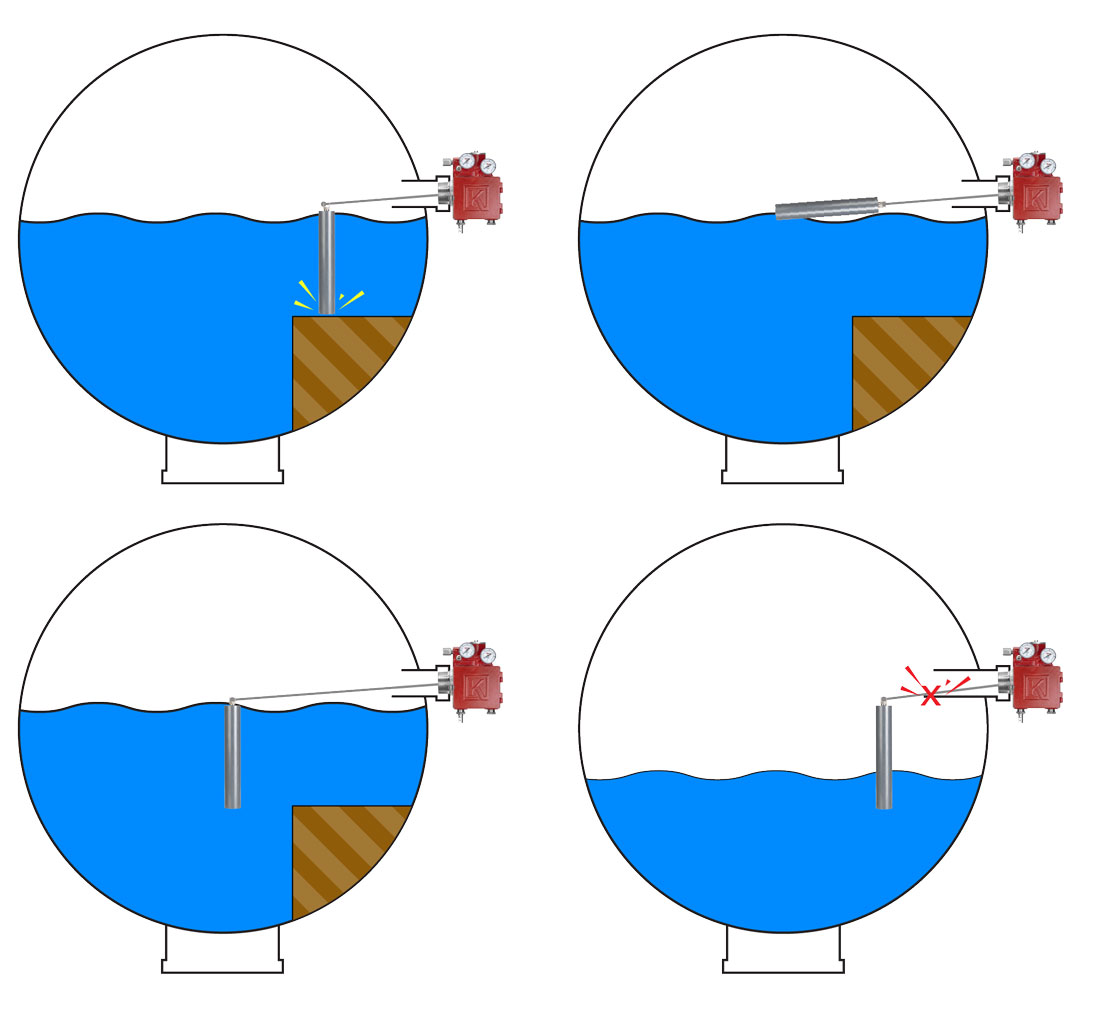
1.4 Displacer Interference
One possible restriction to the arm’s range of motion could be the collar inside the vessel being too long or the diameter too small. If this is the case you can try minimizing the span to get actuations within the smaller travel range.
Likewise, make sure there is clearance for the displacer to travel its full stroke inside the vessel. If there isn’t, you can try switching the displacer orientation from vertical to horizontal or vice versa, or adding or removing arm extensions to avoid the obstructions.
If the displacer is located where it’s getting emulsion dumped on it, this could hold the displacer down and keep the controller from actuating. To remedy this, if there’s room in the vessel, add or remove an extension arm to change the location of the displacer.
Typically diverter plates are used inside the vessel, so this issue is not that common.
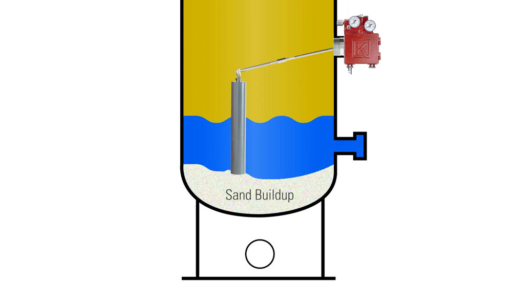
If there’s a lot of sand in your system, it can build up inside the vessel over time to the point where it restricts the downward movement of the displacer. In this case you’ll need to shut in the vessel and remove the sand.
1.5 Sand Buildup
10. Build-Up of Paraffins/Solids in Collar
Solids like paraffins can built up in the collar and in the level controller connection where the arm rotates. Over time the build-up can be so much that it restricts the movement of the arm, not allowing the controller to actuate.
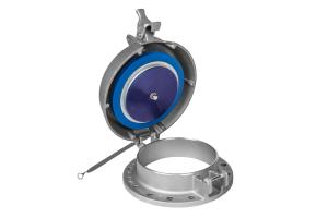
With the Gen 3, you can check for this by removing the clean-out port plug in the back of the connection to inspect for and clean out obstructions. Always bleed the vessel pressure down completely before loosening and removing this plug.
Problem 2: Valve Not Dumping or Closing Fast Enough
If you have the level and span set correctly and the controller is actuating when it should, but the liquid level keeps rising too far when the valve should be dumping, or the liquid level keeps lowering too much when the valve should be closed, the cause could be associated with the level controller, the valve itself, or the vessel.
Here are 12 potential causes, starting with those related to the level controller:
1. Supply/Output/Vent Gas Blockages
Inside the pilot or the communication holes in the controller, any blockages present could slow down the flow of gas to output or to vent, keeping the valve from opening or closing as fast as it should.
To check for contaminants, remove the pilot from the controller and disassemble. Check for any solids or moisture. Blow out the supply, output, and vent communication holes throughout the controller to ensure they are clear. Clean and dry the pilot components before re-assembling.
2. Contamination or Liquid in Supply Lines
If the supply lines coming into the controller are impeded by liquid or other contaminants, the flow of supply gas could be slowed down. If the supply gage fluctuates down when the controller sends output gas, this may be an indication that supply lines are restricted.
Remove the lines and clean them out. Ensure there are no dips in the lines where moisture could collect and pool.
3. Insufficient Supply Gas Pressure
If the pressure of the supply gas is too low, it may not be able to create sufficient force in the actuator to open the valve fully in a Fail Closed valve, or to close the valve fully in a Fail Open valve.
Try increasing the supply gas pressure to see if this fixes the issue. Make sure not to adjust the pressure higher than 45 psi, which is the maximum allowable for the Gen 3 pilot. Pressures above that could potentially rupture the diaphragms inside the pilot.
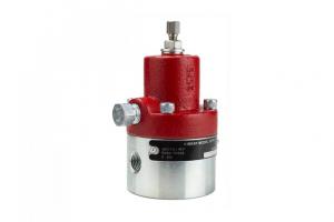
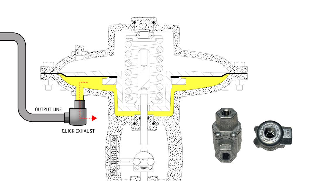
4. Slow Vent
In some applications the vent rate through the Gen 3 pilot may just be less than what you need.
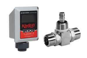
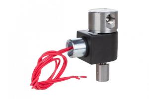
If you want to speed up the vent rate, Kimray offers a Quick Exhaust fitting, which bypasses the pilot during the vent cycle so that the valve can return to its fail position faster.
1.6 Quick Exhaust Fitting
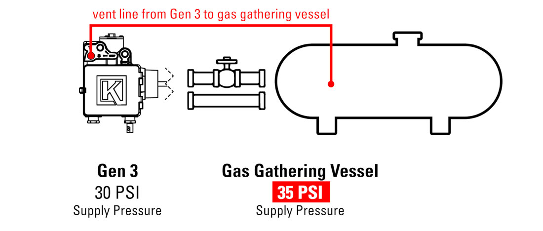
5. Downstream Pressure in Vent Line
If there is pressure downstream in the vent line due to a gas gathering system downstream, the venting rate could be slower than normal, because it is having to push against the downstream pressure as it exits the controller. Additionally, this downstream pressure will not allow the valve actuator to fully vent its pressure. If connected to a Fail Closed valve, there’s a possibility that the valve won’t close fully if the actuator spring doesn’t have enough force to act against the remaining pressure. For the same reason, a Fail Open valve might not be able to open fully.
Increase the supply pressure, but no more than 45 psi, or reduce the downstream pressure of the gas gathering system.
1.7 Vent Line to Gas Gathering Vessel
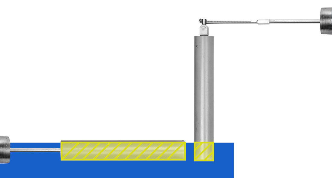
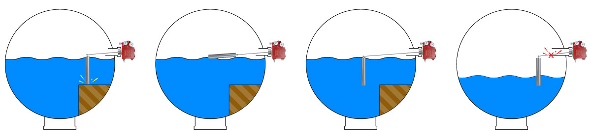
6. Displacer Orientation
When in throttle mode or trying hold a small span in snap mode, the ideal displacer orientation is horizontal, because you get more change in displacement per fluid level change, so the controller reacts sooner than it would in vertical orientation.
If the space in your vessel allows, try converting the displacer from vertical to horizontal orientation.
1.8 Displacer Volume
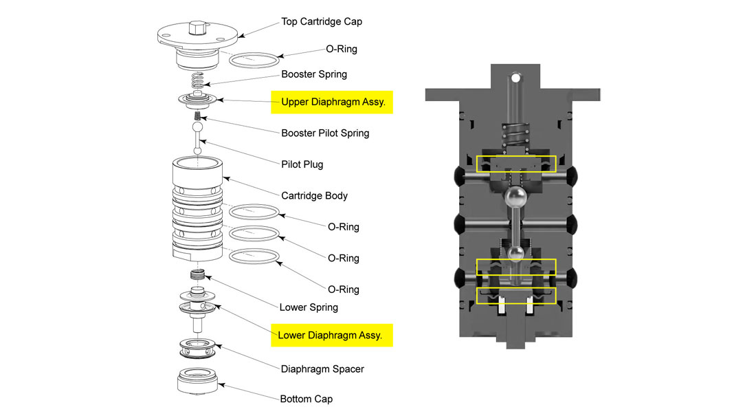
7. Hardened Diaphragms in Pilot
If the controller has been in service for a long time without the elastomers being replaced, the diaphragms in the pilot may have stiffened to the point that they won’t open fully.
If you suspect this is the case remove the pilot from the controller, disassemble, and replace all the elastomers. For your convenience we offer full repair kits containing all soft components that should be replaced at regular service intervals.
1.9 Diaphragms Diagram
8. Valve Inappropriately Sized
An undersized valve could allow the vessel to over-fill, as it can’t dump the liquid fast enough. An oversized valve could be dumping too quickly, not giving adequate time for the actuator to fully close the valve before the liquid falls below a critical level.
Double check sizing of valve to ensure adequate flow rate for process conditions and replace the valve if necessary.
9. Blown Actuator Diaphragm in Valve
If your Fail Closed valve won’t open, or if your Fail Open valve won’t close, it may have a ruptured actuator diaphragm, which is allowing the supply gas into both chambers of the actuator. The best indicator will be gas continuously coming out of the valve actuator’s vent plug.
To fix this, block and bleed the valve, then open up the actuator and replace the diaphragm.
10. Obstruction Inside Valve
This is a rare occurrence, but it is a possibility to consider if nothing else has fixed the situation. That is, an obstruction inside of the valve itself. Sometimes foreign objects make their way into a vessel or line and get caught inside of the valve, restricting its motion, not allowing the valve to close fully or open fully.
To determine whether this could be the issue, block and bleed the valve and remove the trim to inspect for any obstructions.
11. Interference Inside Vessel
If there’s an obstruction inside the vessel not allowing full range of motion of the arm or displacer, this can restrict the actuation of the controller, not allowing full output or full vent flow.
1.10 Displacer Interference
One possible restriction to the arm’s range of motion could be the collar inside the vessel being too long or the diameter too small. If this is the case you can try minimizing the span to get actuations within the smaller travel range.
Likewise, make sure there is clearance for the displacer to travel its full stroke inside the vessel. If there isn’t, you can try switching the displacer orientation from vertical to horizontal or vice versa, or adding or removing arm extensions to avoid the obstructions.
If the displacer is located where it’s getting emulsion dumped on it, this could cause erratic actuations from the controller. To remedy this, if there’s room in the vessel, add or remove an extension arm to change the location of the displacer.
If there’s a lot of sand in your system, it can build up inside the vessel over time to the point where it restricts the downward movement of the displacer. In this case you’ll need to shut in the vessel and remove the sand.
12. Build-Up of Paraffins/Solids in Collar
Solids like paraffins can built up in the collar and in the level controller connection where the arm rotates. Over time the build-up can be so much that it restricts the movement of the arm, not allowing the controller to send full output or full vent flow.
With the Gen 3, you can check for this by removing the clean-out port plug in the back of the connection to inspect for, and clean out obstructions. Remember, always bleed the vessel pressure down completely before loosening and removing this plug.
Problem 3: Vents or Outputs Continuously
If your Gen 3 is constantly sending output or venting gas nonstop, there’s something wrong. The amount of gas that vents during each actuation should be no more than what was in the valve actuator.
Keep in mind though that in throttle mode the controller outputs small amounts and vents small amounts more frequently in order to keep the level consistent, so you will need to differentiate between normal throttle operation and continuous venting.
If your Gen 3 is sending output or venting continuously, here are 2 possible causes and solutions:
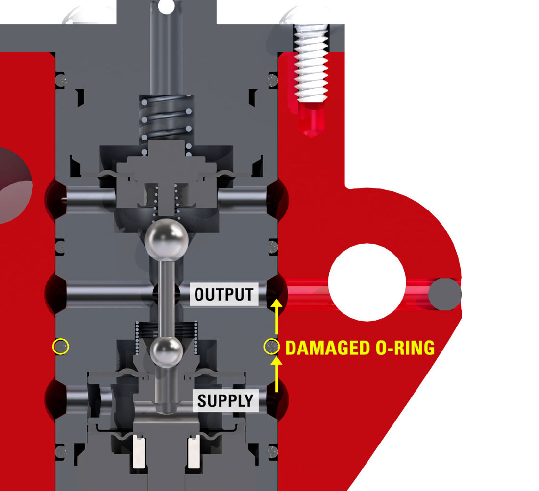
1. Damaged Seals
If any o-rings or diaphragms have been damaged, gas could be able to travel to the vent or output when it shouldn’t. If the supply pressure has been set to greater than 45 psi, this could rupture the diaphragms in the pilot.
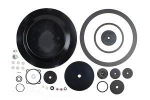
Inspect pilot O-rings and diaphragms. Replace if necessary. Kimray offers a repair kit with all seal components that could ever need replacing.
1.11 Damaged O-Rings
2. Pilot Plug or Seat Dirty
If particles, Teflon tape, wet gas, or any other obstructions have made their way into the pilot, the pilot plug can stick in one position or not fully seat, allowing gas to flow by.
Clean the pilot plug and seat, and ensure the filter is clean. Instrument gas may need upstream filtration or moisture removal.
Problem 4: Gas Emitting Into Atmosphere From Somewhere Other Than Vent Port
In the Gen 3, the only gas that should ever be emitting is through the vent port if it’s set up to vent to atmosphere, or no emissions at all if you have it set up to capture vent gas.
1. Damaged Seals
If your Gen 3 is emitting gas from somewhere other than the vent port, like out of the bottom of the pilot or out the breather hole in the top of the pilot, it’s likely an indication that O-rings or diaphragms in the pilot have been damaged.
Inspect pilot O-rings and diaphragms and replace if necessary.
Problem 5: Oil Going Into Gas Line
If the oil level in your vessel seems to be maintaining at the desired level, within the sight glass range, but somehow oil is making it into the gas outlet line in the vessel, you may have an issue of foaming oil.
1. Foaming Oil
Foaming oil is not dense enough for the displacer to sense its level inside the vessel. The displacer senses the actual liquid oil level, so if the foam continues to rise it could eventually exit the vessel through the gas outlet line. You typically won’t see an indication of foaming oil in the sight glass, because it’s only happening inside the vessel.
If you suspect this might be the issue, defoamers and other chemicals can be used to help prevent foaming but are just temporary solutions. The cause for the foaming could be that there are contaminants in the oil flow stream.
2. How to Weight a Float Ball for Liquid Level Control
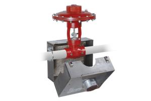
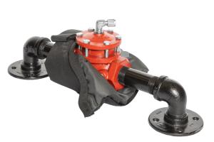
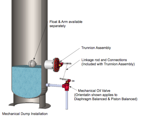
To control the gas, liquid, and oil interface in process equipment, many producers employ a liquid level controller in conjunction with a liquid dump valve.
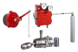
A mechanical level controller consists of three primary parts:
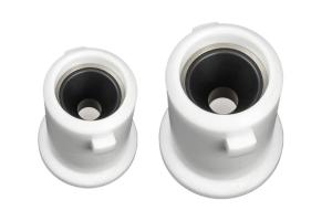
A float ball, which is inserted into the vessel
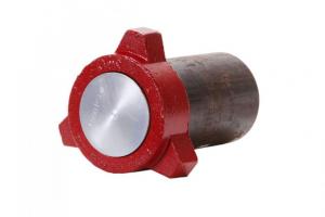
A trunnion, which is bolted onto the exterior of the vessel
An arm, which connects the two
As the liquid level in the vessel rises, the float rises, which drops the rod on the trunnion. This opens the liquid dump valve and sending liquid out of the vessel.
As the liquid level in the vessel falls, the float falls, which raises the rod on the trunnion. This closes off the liquid dump valve and stopping flow of liquid from the vessel.
The dump valve regularly cycles through this routine, adjusting its opening to ensure that the rate of liquid flowing into the vessel matches the rate out of the vessel.
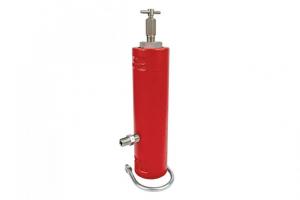
2.1 Example of Float Ball Assembly
In order for the level control system to work correctly, the float ball must be filled with sand or BBs to achieve the appropriate weight to rest at the top of the liquid you are trying to control.
This quick tip helps you weight the float ball for the interface surface.
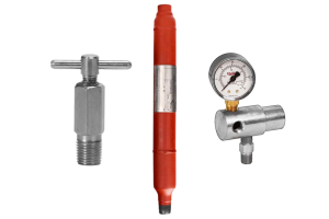
Parts Needed
5-Gallon Bucket
Water
Dry Sand or BBs
Drill
Metal Pipe Nipple
Plastic Funnel
Teflon Tape
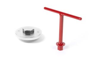
Steps to Weight a Float Ball
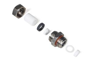
1. Thread a short metal pipe nipple onto the float ball to protect the threads
This will prevent incidental damage and ensure a good seal.
2.2 Install Brushing or Metal Pipe Nipple
2. Drill a hole through the end of the float ball where the coupling is
Typically a half-inch hole will work. This is where you will pour in the sand.
2.3 Drill a Hole Through the End of the Float Ball
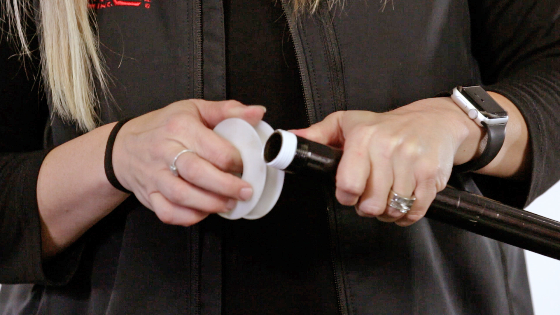
3. Using a funnel, pour sand into the float ball
Make sure to use dry sand. If you overfill, it’s much easier to remove dry sand from the float ball than wet. (Note: this is one reason some choose to fill the float ball with BBs.) The total weight needed for a 7" x 12" float ball with float rod is approximately 13.5 pounds, but the weight needed will vary.
2.4 Use Funnel to Fill Float Half Full
4. Insert the float ball and float rod into a bucket of fresh water
If the float ball has surface area protruding from the water level, it’s not heavy enough so you’ll need to add more sand. (Note: make sure you thread on the float rod and include it as part of your weight.)
If the float ball is fully submerged up to the float rod coupling, you are ready to move to the last step.
2.5 Test the Weight in a Bucket
5. Tape the threads and attach the float rod
Do this very carefully to achieve a good seal. When the float is under pressure, water can easily be forced in, so make sure to tape well and tighten the float rod so it won’t ingress.
Kimray is dedicated to investing in educational resources for the oil and gas industry, and we hope this collection of content has been helpful. If you have any feedback on this learning path, please fill out our short feedback survey.