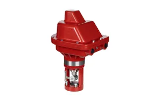
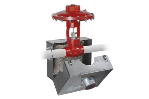
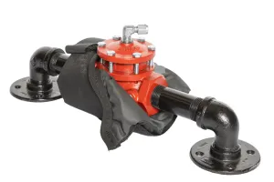
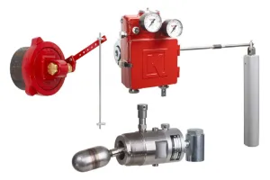
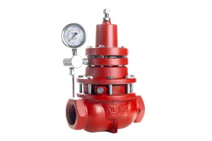
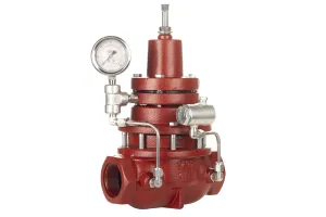
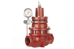
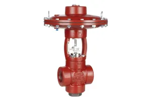
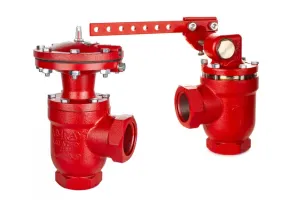
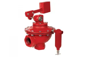
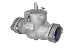
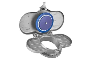
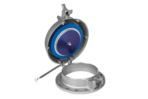
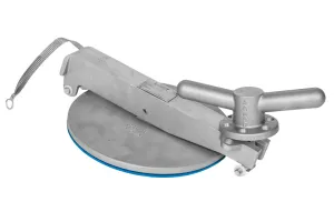
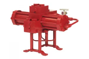
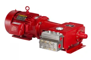
The Weight Operated Dump Valve is designed to hold liquid level in production vessels such as heater treaters, free water knockouts, and saltwater disposal systems.
In this video, we’ll be performing routine maintenance with a Kimray Repair Kit for a 2” Weight Operated Dump Valve.
CAUTION: Before any service, be certain that the valve is fully isolated and that all pressure upstream and downstream has been relieved. Use bypass valves or fully shut off the process. Be sure that any operating or instrument gas lines have been disconnected.
SAFETY: Nitrile gloves are highly recommended when working with and handling greases and chemicals to prevent skin irritation. Use all appropriate PPE as required by your company guidelines.
NOTE: If you have an old stuffing box design, you will need a stuffing box replacement kit in addition to a repair kit.
Some components will be duplicated, but you will need the replacement kit primarily for the stuffing box and stuffing box nut.
Tools & Components Needed
| End Connection (Standard or Corrosive | 2" | 3" | 4" | 6" |
|---|---|---|---|---|
| Repair Kit | REL | REM | REN | REP |
| Seat Wrench Tool | 384SW | 385SW | 386SW | 1771SW |
| Seat (if damaged) | 384DEL | 385DEL | 386 | 1771 |
| Stuffing Box Replacement Kit | RZL | RZM | N/A | N/A |
| Orifice Reducer Seat Assembly | 7932DEL | 7934DEL | N/A | N/A |
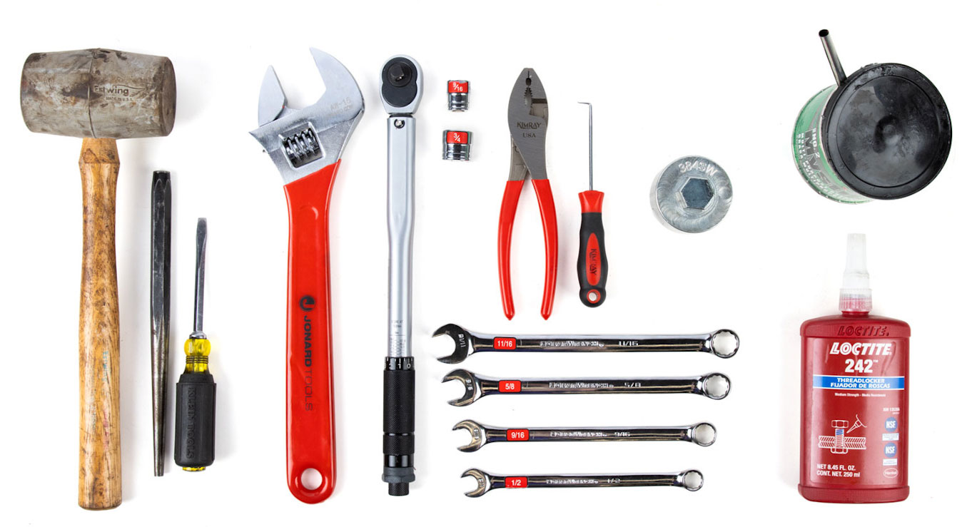
Tools
- Adjustable Wrench
- 1/2” Wrench (set screw)
- 9/16” Wrench (various)
- 5/8” Wrench (drip pot nipple)
- 11/16” Wrench (various)
- Torque Wrench
- 3/4” Socket (pivot)
- 7/8” Crowfoot (diaphragm bolt)
- Pliers (snap rings)
- Pick
- Large Center Punch (if components are stuck)
- Flathead Screwdriver (if components are stuck)
- Mallet (if components are stuck)
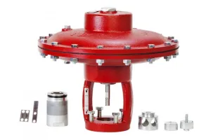
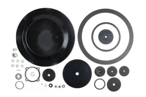
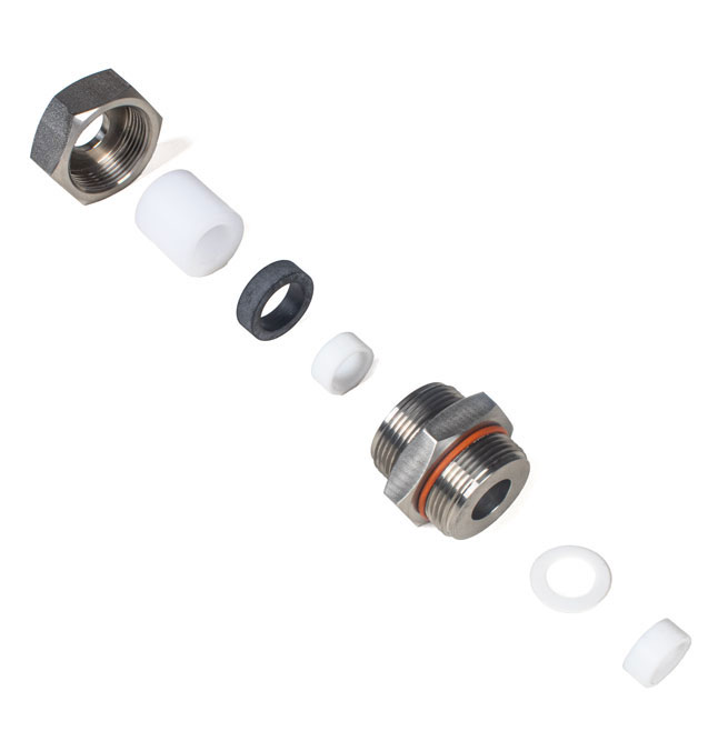
Kimray Components
- Repair Kit
- Seat Wrench Tool
Chemicals
- All-purpose grease (O-rings/gaskets)
- Blue Loctite (drip pot nipple/bleed valve)
Weight Operated Dump Valve Disassembly
This valve can be repaired inline, but if it has been removed from the piping, start by securing it in a vise.
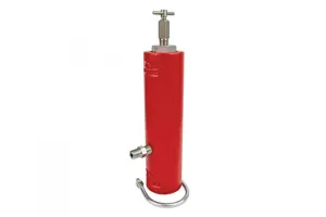
Drip Pot
- Use a 5/8” wrench on the nipple connecting the drip pot to the valve body (you do not need to separate the nipple from the drip pot).
- There are no repair kit components for the drip pot, but it’s important to clean this out when doing maintenance. If you do not remove the drip pot, you still must remove the pressure line.
Weight & Lever
- Remove the weight by loosening the bolt with a 9/16” wrench and sliding the weight off.
- Remove both bolts from the lever hub with an 11/16” and 9/16” wrench and remove the lever.
- Loosen the set screw with a 9/16” wrench and then remove the lever hub from the shaft. If the lever hub is difficult to remove from the shaft, gently tap it on each side with a mallet to loosen and remove. Make sure you’re not striking too hard at an angle to damage or bend the shaft.
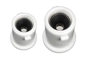
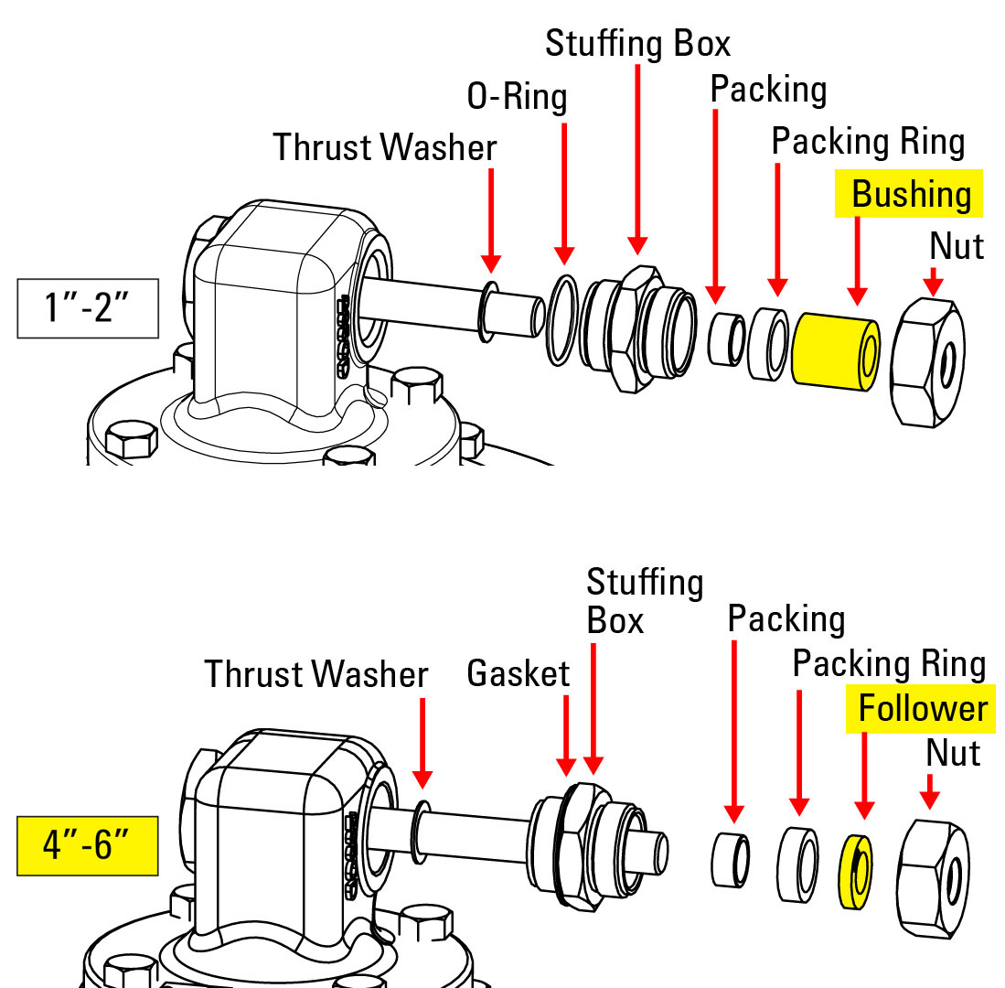
Shaft, Stuffing Box & Trunnion Plug
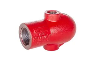
- Using an adjustable wrench, remove the trunnion plug.
- Remove and discard the O-ring from the trunnion plug.
- On 4” and 6” models, this will be a gasket and not an O-ring. It also may be stuck to the valve instead.
- With a pick, screwdriver or similar tool, remove and discard the bushing from the shaft.
- With the adjustable wrench, next remove the stuffing box nut.
- Unthread the stuffing box, then pull it out with the shaft. If it’s stuck, tap the shaft out from the opposite end using a large center punch.
- Then separate the shaft from the stuffing box.
- Remove and discard the Teflon thrust washer from the shaft.
- Remove and discard the O-ring from the stuffing box.
- Remove and discard the bushing, packing ring and packing from the stuffing box.
- On 4” and 6” models, there will be a follower instead of a packing ring. Keep the follower, as it is not part of the repair kit.
Bonnet & Trunnion Hub
- Remove the 4 bolts from the bonnet with a 9/16” wrench and remove the bonnet. If it’s stuck, pry it gently with a flathead screwdriver.
- Remove and discard the snap rings with pliers.
- Next, remove the pin and trunnion hub.
Stem & Small Diaphragm Assembly
- Unthread the diaphragm bolt with a 7/8” or adjustable wrench and remove the stem assembly from the body, pulling straight up so the pin does not fall out into the body.
- Pull the pin from the stem assembly.
- Then pull the stem out through the diaphragm bolt.
- Then remove and keep the diaphragm retainer.
- Remove and discard the diaphragm from the diaphragm bolt.
Housing, Diaphragm & Removable Seat
- Using a 9/16” and 11/16” wrench, remove the housing bolts.
- Remove the housing. You may need to pry it apart with a flathead screwdriver.
- Pull up on the diaphragm to remove the entire assembly from the body. Set this aside for now.
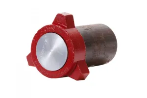
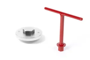
- Next, we’ll inspect the removable seat. If it has no noticeable damage or potential leak paths, and you do not have the Kimray seat wrench, it’s best to leave the seat in place.
- If you are removing the seat, use the Kimray seat wrench and an adjustable wrench.
- Discard the gasket from the removable seat.
- Take the body out of the vise and replace it with the diaphragm assembly upside down, securing the neck of the diaphragm plate in a vise.
- Unscrew and remove the pivot bolt with an adjustable wrench.
- Then remove the ratio plug, seat, and seat disc. If they’re stuck together, use a punch to separate the ratio plug and a flathead screwdriver to remove the seat. Discard the seat, keep the ratio plug and seat disc.
- Remove and discard the diaphragm.
Cleaning & Inspection
With the valve fully disassembled, next we’ll clean and inspect the components.
- Shaft: Inspect that the shaft is not bent. If it is bent, it will need to be replaced.
- Body: If you removed the seat, inspect for signs of corrosion where it meets the valve body. If there is corrosion, it won’t seal properly, and you will need a new valve body. Use an air nozzle to blow out the particles from inside the body. Any loose particles in the seat area could allow for leakage.
- Housing: Verify that the housing communication hole is clear and free of debris.
- Drip Pot: Examine and clean the drip pot and needle valve.

Lastly, use a parts washer or wire brush to clean the following parts:
- Lever Hub
- Stuffing Box Nut
- Stuffing Box
- Trunnion Plug
- Bonnet
- Stem
- Housing
- Removable Seat (metal only)
- Body
Assembly
We are now ready to assemble the valve.
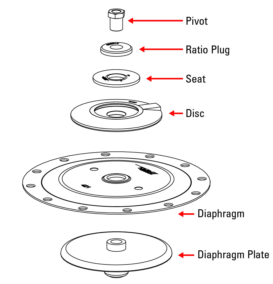 Diaphragm Assembly
- Secure the diaphragm plate in the vise.
- Stack the following components on top:
- Diaphragm (#421/422) (Kimray logo facing up)
- Diaphragm Disc (lettering facing up)
- Seat (#7502HSN/7503HSN) (reversible)
- Ratio Plug (part numbers facing up)
- Pivot
- Tighten the pivot with a 3/4” socket to 10 ft-lbs.
REMOVABLE SEAT
- Remove the diaphragm assembly and place the body into the vise.
- If you removed the seat, apply all-purpose grease to the seat area of the body.
- Flip the removable seat upside down and apply all-purpose grease.
- Then install the (#387/388) gasket.
- Install the seat into the body with the Kimray seat wrench. Do not over tighten the seat or the gasket can tear.
HOUSING
- Place the diaphragm assembly on the body with the seat disc facing down, aligning the bolt holes with the diaphragm.
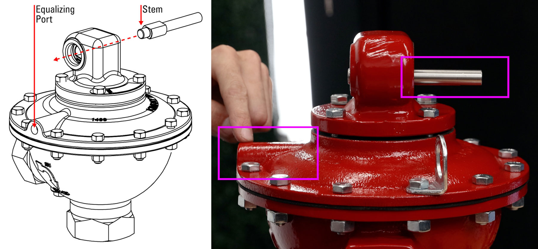
- Then place the housing on top with the equalizing port at 90° counterclockwise from the valve inlet.
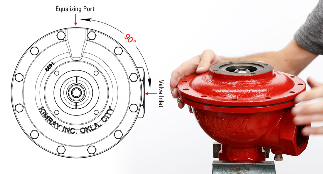
- Insert all housing bolts and thread on the nuts by hand. Make sure the lifting rings are placed 180 degrees from each other.
- Tighten the bolts with a 9/16” socket and 11/16” wrench to 25 ft-lbs. Use a crisscross pattern to avoid any misalignment.
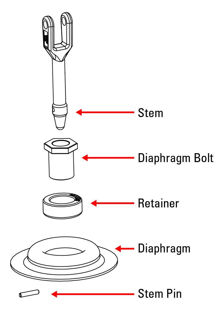 Stem Assembly
- Place the diaphragm retainer into the (#416/417) diaphragm with the part numbers facing up.
- Then insert the diaphragm bolt through the retainer.
- Next, insert the stem.
- Then slide the stem pin through the lower end of the stem.
- Hold the stem pin in place and install the stem diaphragm assembly into the diaphragm plate.
- Tighten the diaphragm bolt by hand, then tighten fully with an adjustable wrench but be carefully not to overtighten. Kimray recommends a 7/8” crowfoot wrench to 10 ft-lbs.
Hub Assembly
- Insert the link pin through the stem and hub link.
- Press the two (#941/975) snap rings into place; one on each side of the link pin.
- Orient the head of the trunnion hub towards the valve inlet with the arrow pointing up.
Bonnet
- Lift the trunnion hub slightly and place the bonnet over it. Align the rounded side of the bonnet with the valve inlet.
- Start the 4 bonnet bolts by hand and then tighten with a 9/16” socket to 25 ft-lbs. Use a crisscross pattern to avoid misalignment.
Stem
- With the flat edge of the long end of the shaft facing down, insert the shaft through the trunnion hub. The long end will be sticking out the side opposite the equalizing port.
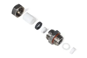
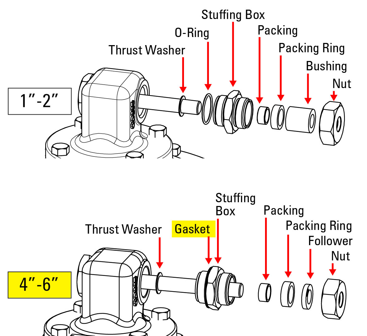
Trunnion Plug & Stuffing Box
The trunnion plug and stuffing box assemblies are slightly different for 2”-3” valves compared to 4”-6”.
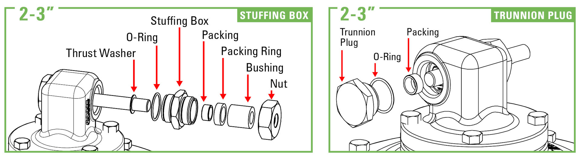
2”-3” Valves
- Apply grease to the threads of the trunnion plug and stuffing box to avoid damaging the O-rings. On the stuffing box, the O-ring will be on the side with the smaller opening.
- Install an (#2131/5226) O-ring on the trunnion plug.
- Then install another (#2131/5226) O-ring on the stuffing box.
- Apply grease to both O-rings after installation.
- Install a (#7662/355) packing on the short end of the shaft.
- Place the trunnion plug over the shaft and packing, then thread it into the bonnet and tighten with a 1-3/8” socket or adjustable wrench (Kimray recommends 25 ft-lbs.)
- Slide the (#360/361) thrust washer onto the shaft.
- Then slide the stuffing box over the shaft and thread it into the bonnet with an adjustable wrench. (Kimray recommends 25 ft-lbs.)
- Grease the inside of the stuffing box and the end of the shaft.
- Push the (#7662/355) packing into the (#351/352) packing ring.
- Then insert them into the stuffing box.
- Follow with the (#7915/7916) bushing. Using the bushing, push the packing all the way into the stuffing box.
- Thread the stuffing box nut onto the stuffing box, just hand tight, then another ½ turn with an adjustable wrench. Over-tightening the stuffing box nut can prevent the shaft from rotating.
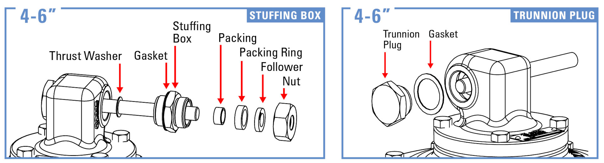
4”-6” Valves
- Grease both sides of both (#366/1789) gaskets.
- Place one gasket on the trunnion plug and one on the stuffing box.
- Thread the trunnion plug into the bonnet and tighten with a 1-3/8” socket or adjustable wrench (Kimray recommends 25 ft-lbs.)
- Slide the (#362/1788) thrust washer onto the shaft.
- Grease the inside of the stuffing box and the end of the shaft.
- Push the (#356/1786) packing into the (#353/1787) packing ring.
- Then insert them into the stuffing box.
- Next, place on the packing follower.
- Slide the stuffing box over the shaft and into the bonnet.
- Thread the stuffing box nut onto the stuffing box, just hand tight, then another ½ turn with an adjustable wrench. Overtightening the stuffing box nut can prevent the shaft from rotating.
Lever Hub, Lever & Weight
- Attach the lever hub to the end of the shaft with the lever arm channel facing out.
- Tighten the set screw securely with a 9/16” wrench.
- Attach the lever with a 9/16” and 11/16” wrench on both bolts.
- Place the weight on the arm and secure it in place with a 9/16” wrench.
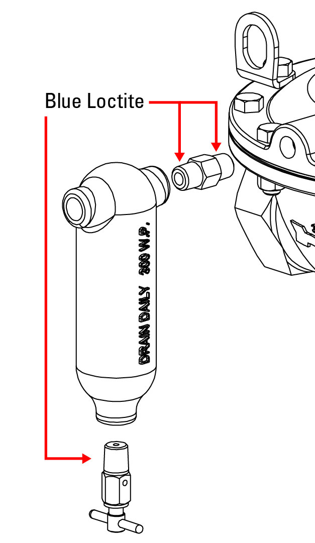
Drip Pot
- If the nipple connector was removed from the drip pot, apply Blue Loctite to the nipple before tightening it into the drip pot.
- Apply Blue Loctite to the other end of the nipple as well.
- Thread the nipple and drip pot into the housing equalizing port until tight and the drip pot is facing down; 3-4 full turns.
- If you removed the bleed valve for cleaning purposes, apply Blue Loctite to the threads before threading it into the bottom of the drip pot.
If you have any questions about Weight Operated Dump Valves or the Kimray tools used, contact Kimray Product & Customer Service.