Let’s take a trip around a well site and explain what each piece of equipment is doing to separate the oil, gas, and water being produced.
Well Head
The rod pump is positioned in the well bore where it brings the resource out of the ground and into the well head. This pumping unit attaches to a series of rods, and at the bottom of the rod is a pump. It’s a sleeve with a plunger inside with a check valve ball at the bottom and a check valve at the top.
This emulsion of oil, water, and gas is brought to the surface through the flow line tubing. The production equipment could be near the equipment or in some cases over a mile away before it gets to the processing equipment.

2-Phase Vertical Separator
The first vessel the flow line reaches is a 2-phase vertical separator. This separates gas from the water-oil emulsion.
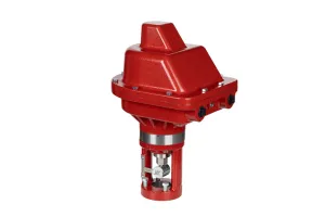
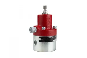
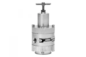
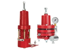
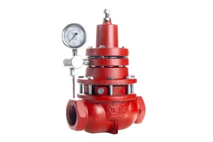
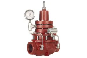
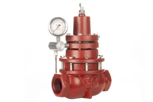
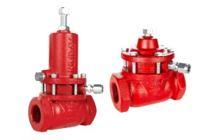
Natural gas, being lighter than liquid, rises to the top of the vessel where it begins to separate from the well stream. The natural gas flows through the outlet on the top of the vessel and into a Kimray back pressure regulator. The back pressure regulator holds constant pressure on the vessels to allow it to move liquids to the next destination.
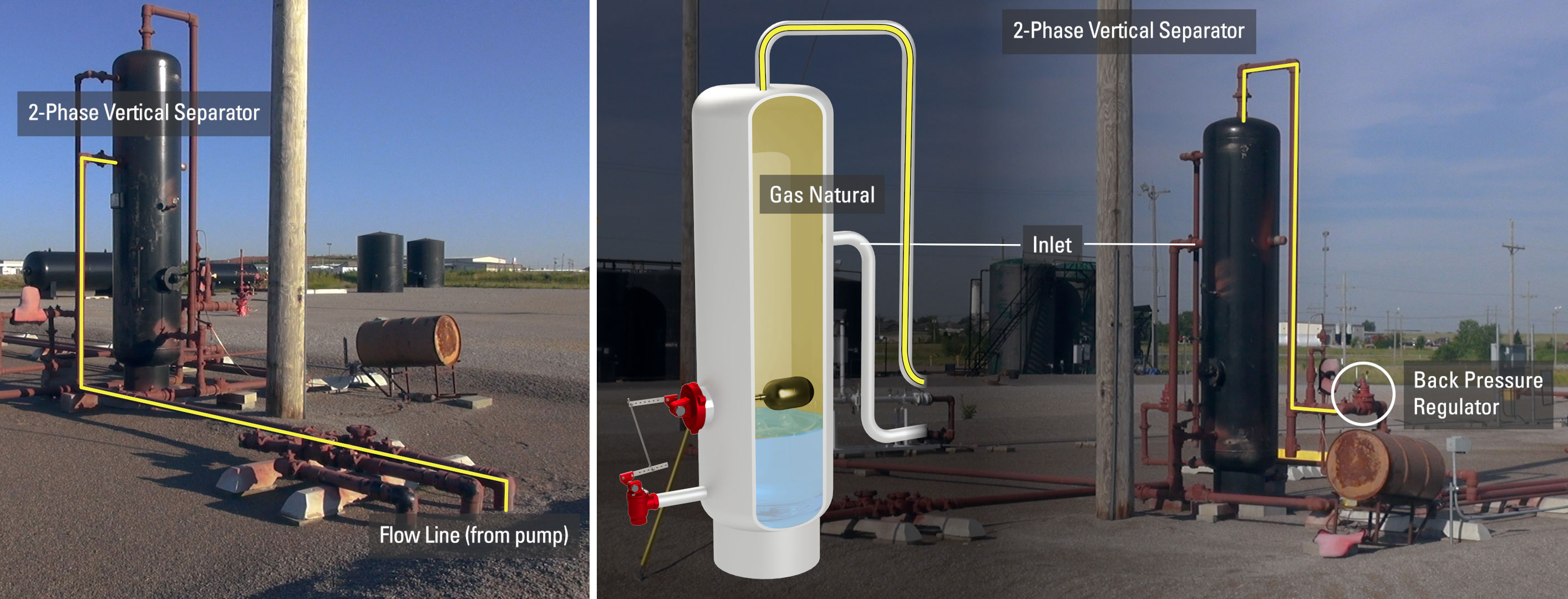
Any gas over the setpoint will be sent to the meter run to be measured, recorded and sold, typically to a midstream company. The meter run allows the producer to make money from the resources brought to the surface.
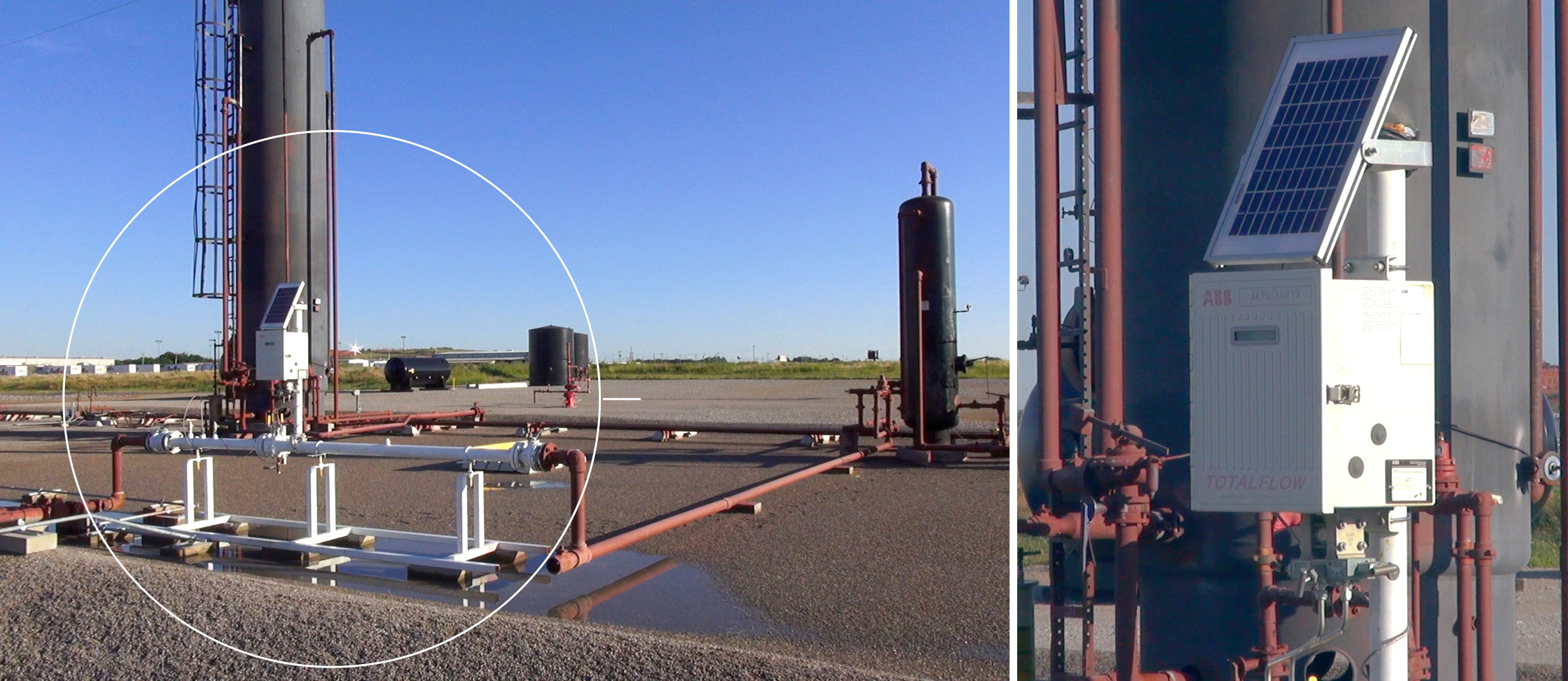
Another valve related to the sales line is the flare valve. This back pressure regulator is installed in case there is maintenance on the sales line or if in the future they tie in a new well and pressure backs up on the existing location. The flare valve is set at a higher setpoint than the sale valve. If that pressure setpoint is met, the valve opens sending the gas to a combustor or flare to be incinerated until the condition changes.
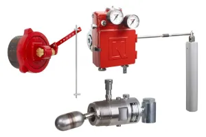
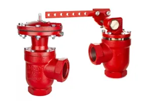
The fluid that was brought into the two-phase separator from the flow line is a mix of oil and water. This emulsion drops to the bottom of the vertical separator and is controlled by a liquid level controller. In this setup, a float ball is connected to a dump valve with a mechanical link. As the fluid rises it lifts the float ball in the vessel pushing down on the mechanical linkage which then in turn opens the mechanical dump valve. This allows the oil, water and any solids in the liquid to flow out of the pipe.
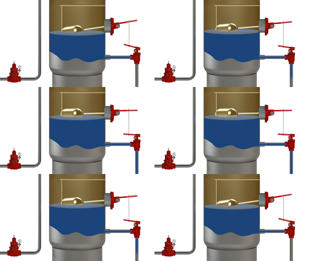
This dump line could go directly to a storage tank, but in this case the producer needs to further process the emulsion to make it sellable. It is sent downstream for further processing at the next vessel: a heater treater.
Heater Treater
The emulsion flows through the inlet on the top of the heater treater where it hits a baffle. Natural gas still in the fluid begins to separate and flow out of the pipe at the top of the vessel and down to one of two valves. Like in the 2-phase separator, the valves and piping will send the gas either to sales or flare.
The emulsion in the heater treater is funneled through a down comer pipe to the bottom of the vessel surrounding the Fire Tube. Because of the heat from the fire tube, the process fluid molecules relax, allowing the oil and water to separate. Oil is lighter in gravity than water and will float on top of the water.
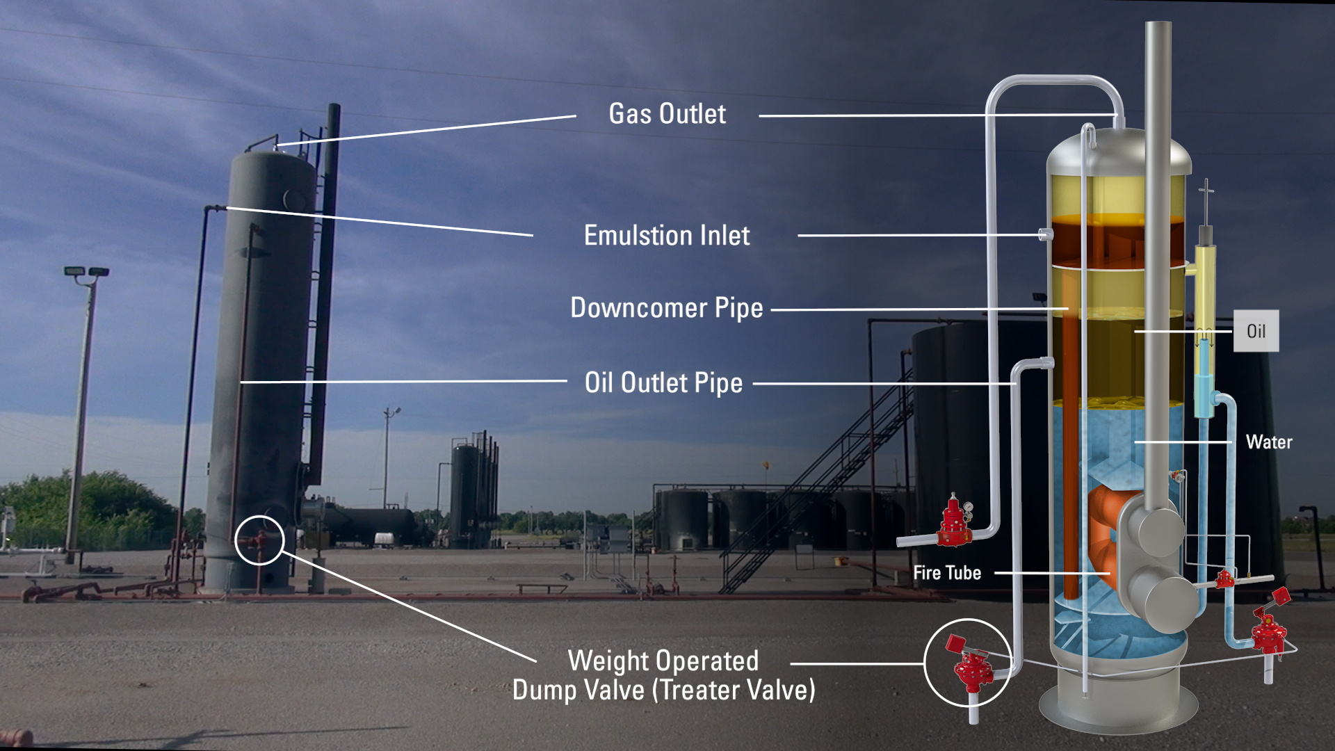
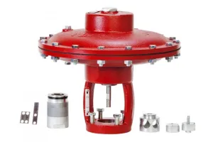
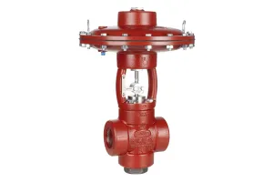
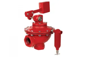
As it reaches the setpoint, oil comes down the oil outlet pipe to a Kimray weight-operated dump valve, or treater valve. This valve only controls the liquid in the downcomer pipe it does not control the liquid inside the vessel. As the height in the pipe meets the desired level, the valve will open, sending the oil into the storage tank. A midstream company will purchase this crude oil from the producer and transport it to a refinery for further processing.

Salt water is produced when the emulsion is processed with heat from the fire tube. A water siphon is used to control the level of salt water in the vessel. This produced water goes up a pipe into the siphon box, sometimes called a weir box. As the water reaches the siphon nipple, the water spills over and goes down the pipe to another weight-operated dump valve or treater valve.
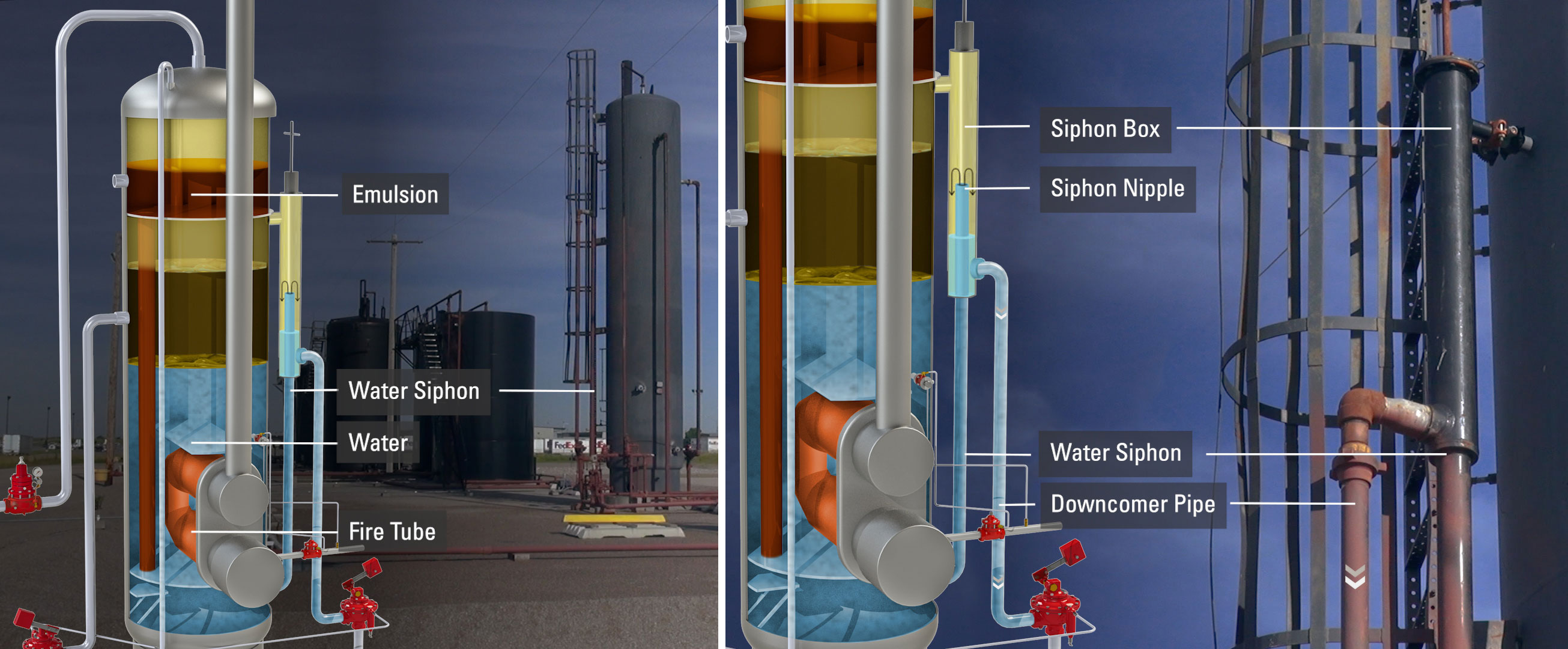
Again, this valve controls only the level in this downcomer pipe.
Store & Recirculation
When the valve opens, the water goes to either a fiberglass storage tank or on this location, a water treatment plant for further processing.
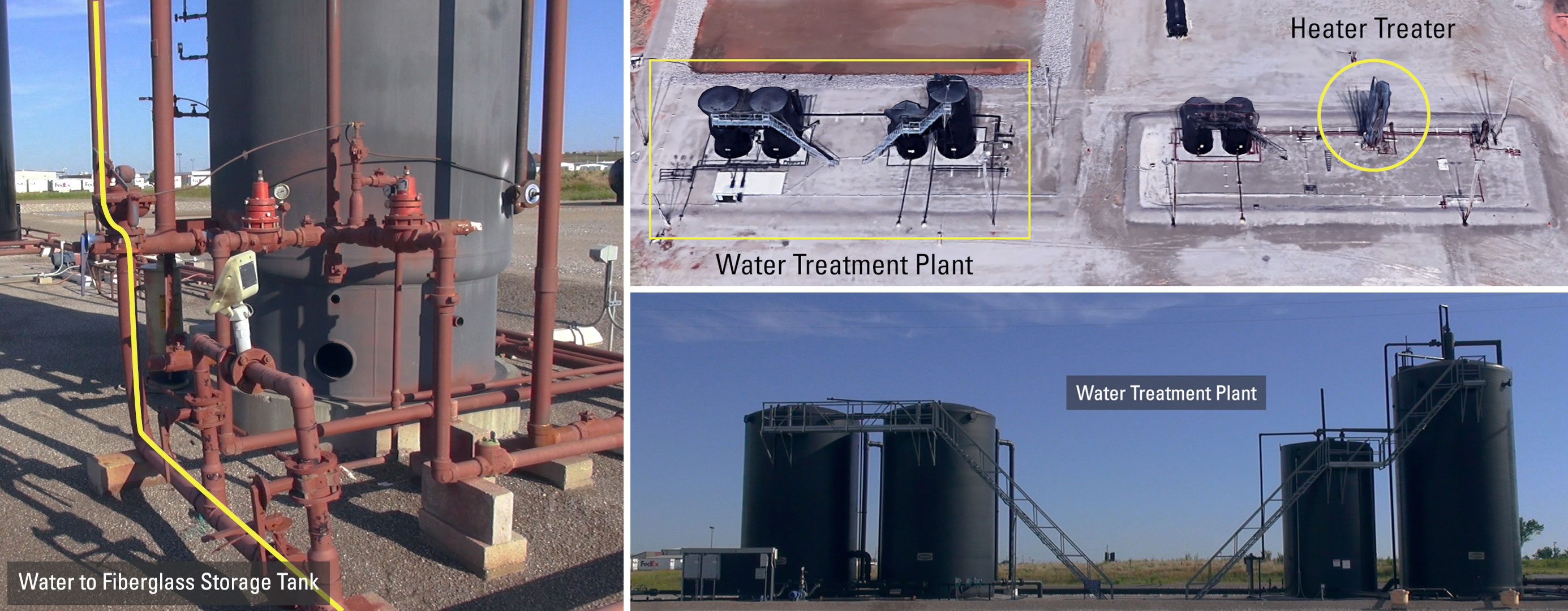
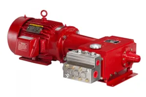
This is a recirculating line which goes into the recirculating pump. It then goes back to the inlet of the treater to run through the whole process again for more processing.
There are many other pipelines on location, many of them are bypass lines. Some bypass the separator others bypass the heater treater. There is also a pipeline to bypass both.

To schedule training over Kimray related topics, contact your local Kimray store. We can help set up sessions for you or your entire team.
The purpose of all these vessels and Kimray components is to take the raw, unusable products and turn them into important and profitable resources.
