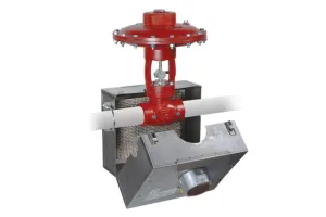
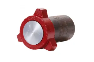
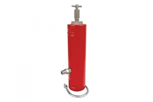
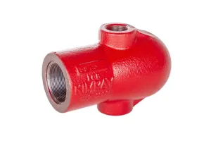
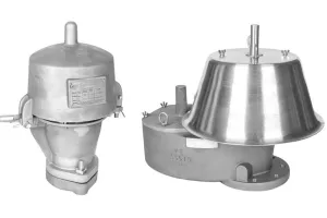
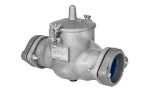
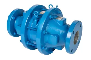
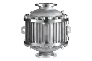
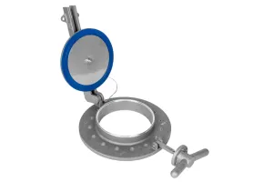
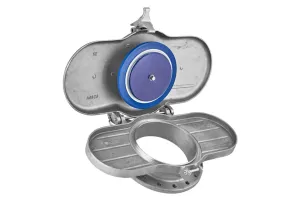
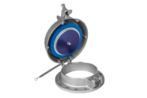
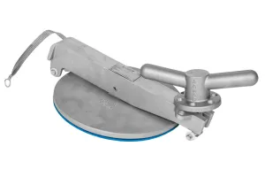
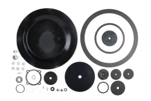
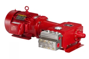
Kimray has partnered with LaMOT Valve & Arrestor to provide safe, reliable solutions for your well site storage tanks. In this video, we’re going to look at how to maintain, clean and assemble LaMOT deflagration flame arrestors.
WHY MAINTENANCE IS IMPORTANT
To keep your flame arrestor operating at peak performance, it’s important to inspect and maintain the flame bank elements at least once a year. Depending on your application, you may need to do it more often. You’ll also want to inspect it anytime you notice excessive pressure drops or if you believe your arrestor has been exposed to a flame front.
After a flame event, it’s critical to replace the flame arrestor element. The flame arrestor performance cannot be guaranteed after the first flame event.
Now let’s look at how this is done on the 3” inline deflagration flame arrestor.
STEP-BY-STEP MAINTENANCE
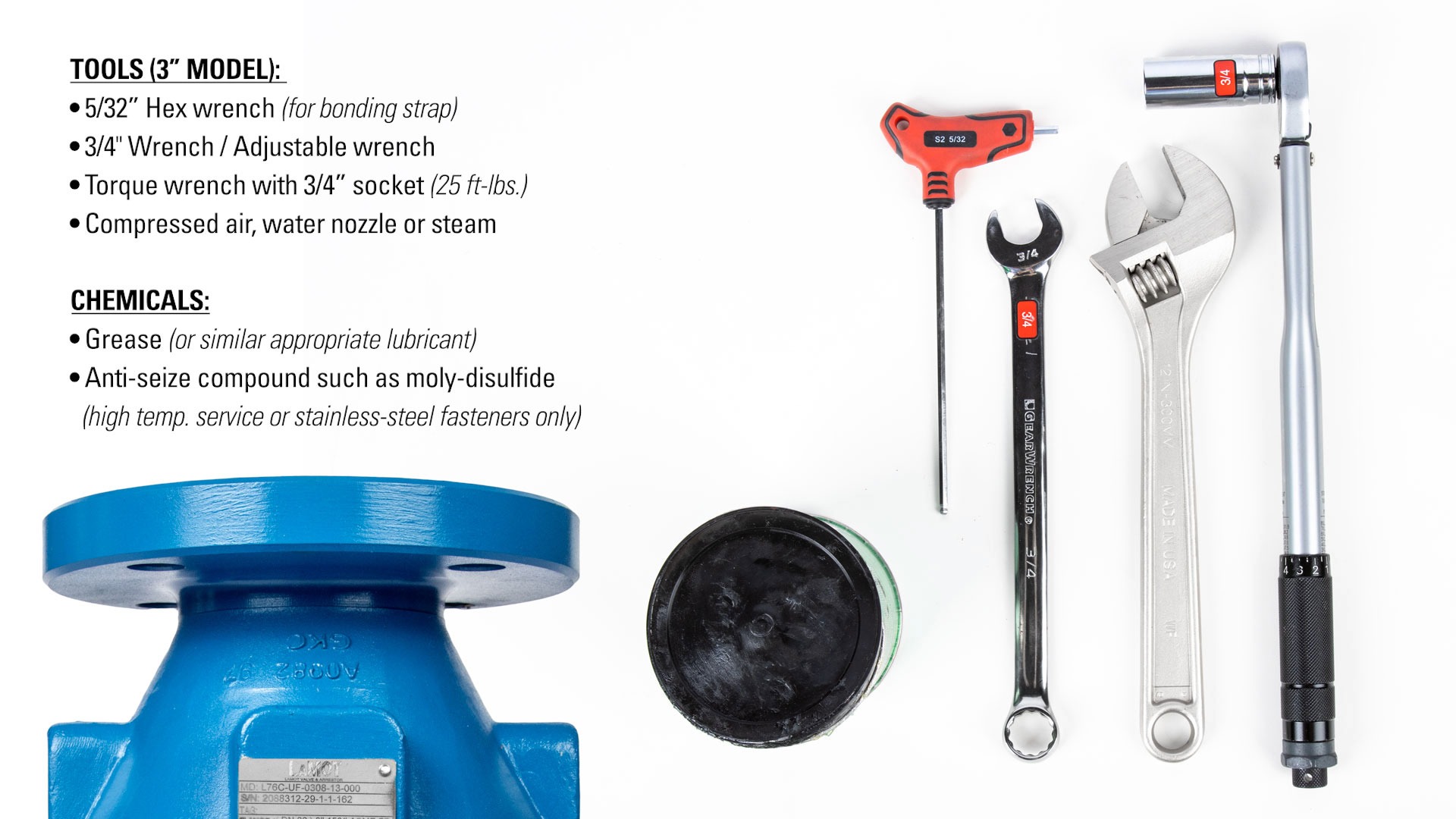
Tools Needed (3”)
- 5/32” Hex wrench (for bonding strap)
- 3/4" Wrench (for 3” models)
- Torque wrench & 3/4” socket (25 ft-lbs.)
- Compressed Air, Water Nozzle or Steam
- Grease (or similar appropriate lubricant)
- Anti-seize compound such as moly-disulfide (for high temp. service or stainless-steel fasteners only)
Commonly Replaced Parts
| SIZE (Connection Size x Housing Size) | ASSEMBLY PN |
|---|---|
| 2” x 6” | LKFBFH060200050011000000 |
| 3” x 8” | LKFBFH080200050011000000 |
| 4” x 10” | LKFBFH100200050011000000 |
| 6” x 16” | LKFBFH160200050011000000 |
| 8” x 20” | LKFBFH200200050011000000 |
| 10” x 24” | LKFBFH240200050011000000 |
| 12” x 28” | LKFBFH280200050011000000 |
CAUTION: The procedures in this video are intended for general informational purposes only. Always follow your company’s safety requirements, policies, and applicable regulations when performing any maintenance or repair.
Before starting any repair or maintenance activities:
Review and follow all WARNING notes found in the LaMOT Valve and Arrestor’s Installation, Operation, and Maintenance (IOM) guide for your specific product.
Wear all required personal protective equipment (PPE), including approved eye protection, steel toe safety shoes, and protective gloves to protect against exposure to chemicals and other hazardous materials.
Failure to use appropriate PPE or follow proper procedures can result in serious injury or death.
DISASSEMBLY
- First, remove one side of the bonding strap with a 5/32” hex wrench.
- Make sure the weight of the flame bank assembly is supported before removing the studs and nuts.
- You can use the housing handles or lifting eyes;
- Or, depending on the size of your arrestor, you can leave the bottom four studs and bolts in place after loosening them. On this 3” model, these bottom studs will not obstruct the removal of the flame bank but also support the weight during removal.
- Next, loosen the bolting nuts with two ¾" or adjustable wrenches on each opposing nut. We will be fully removing the top four bolts and only loosening the remaining.
- To separate the base halves, you may need to use the separating nuts (or jackscrews for 8”-12” sizes) to push the two bases from one another. Use spacer blocks or spreader tools if necessary to safely secure the base halves so the housing is free for removal.
- Remove the flame bank element housing assembly for inspection.
INSPECTION & CLEANING
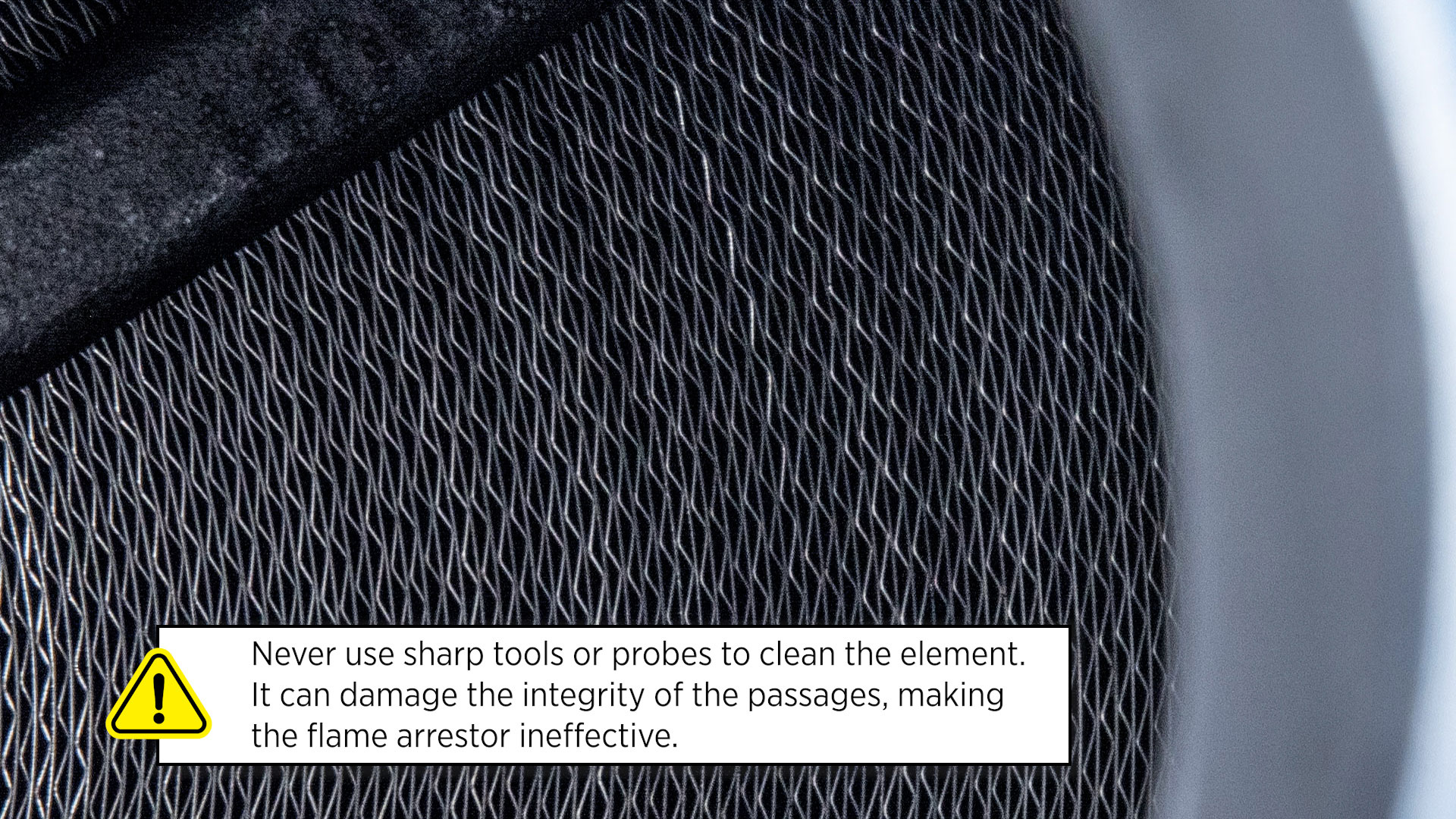
CRITICAL WARNING: It's critical that you never use sharp tools or probes to clean the element. It can damage the integrity of the passages, making the flame arrestor ineffective.
Inspect for Damage
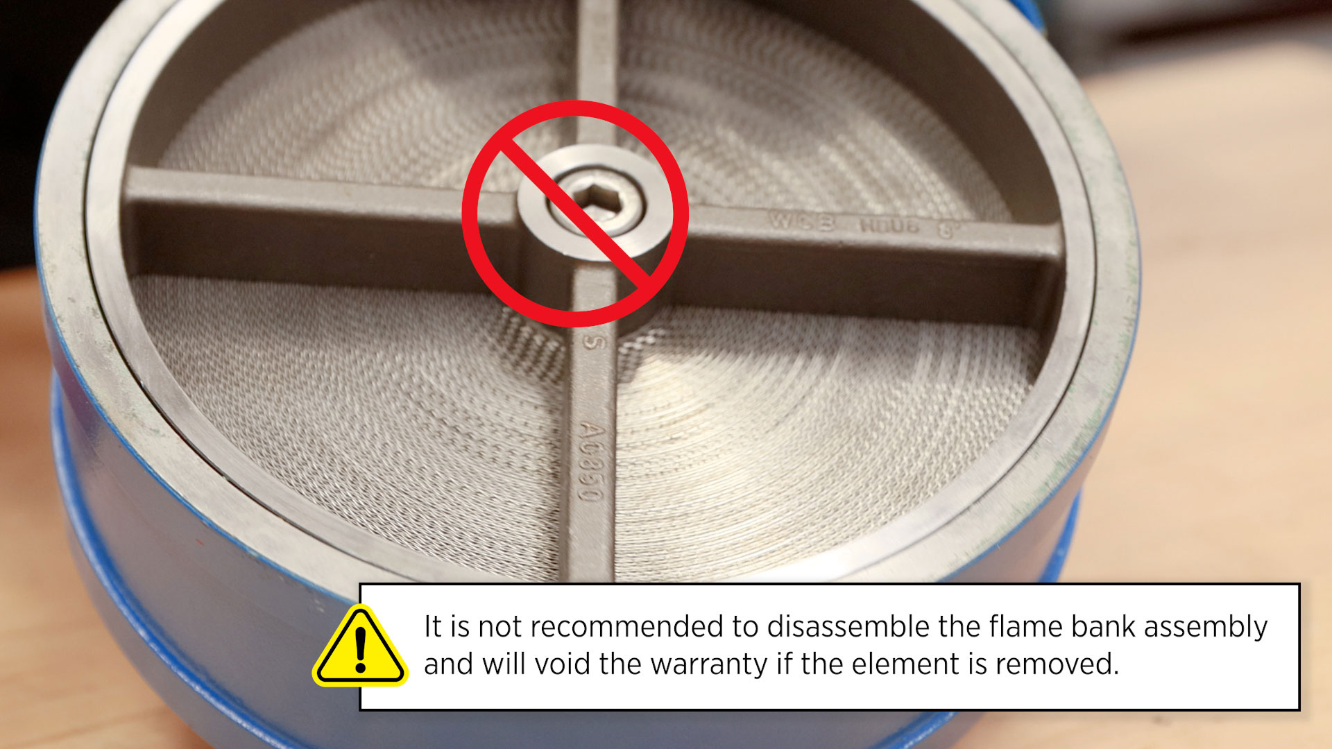
- Element & Supporting Grids: Check both sides of the element and supporting grids for any signs of damage, corrosion, or buildup. If the element looks damaged, replace it immediately. It is not recommended to disassemble the flame bank assembly and will void the warranty if the element is removed.
- Gaskets: Next, inspect the gaskets for damage and replace them if necessary.
- Gasket Seating Surfaces: Inspect the gasket seating surface of the flanges. They must be clean, flat and free of scratches, corrosion and tool marks.
Replacements
To order a replacement:
LVA Headquarters:
281-295-6800 or LVASales@lamot.com
Kimray, Odessa, TX Authorized Repair Center:
432-332-1438 or odessasales@kimray.com
Clean Element
View the element openings through a light source to check for clogs or obstructions. If it’s dirty, it can be cleaned by one of three methods. Make sure you have the appropriate PPE before using any of these methods.

- Compressed Air: First, you can use compressed air equal to or less than 80 psig.
- Water Purge: You could also use a water purge method with a low-pressure spray nozzle equal to or less than 40 psig.
- High Pressure Steam: If you need to use high-pressure steam, make sure not to focus the stream too tightly as it could damage the element.
- Non-flammable Degreaser Wash: Lastly, you can use a non-flammable degreaser wash, followed by compressed air until dry.
ASSEMBLY
Now we will assemble the housing, bases, and gaskets.
- First, install the gaskets.
- Add a small amount of grease to the textured side of the gasket face to make installation easier.
- Place the gaskets on the flanges, centered with the bolt circle or counterbores if present.
- Next, place the flame bank assembly into position.
- Ensure the lifting handles or lifting eyes are on top. The flame bank assembly is bi-directional and can be installed either way; there is not a front or back.
- Lubricate all studs with grease or a similar lubricant.
- For high-temperature service, or if you’re using stainless steel fasteners, apply an anti-seize compound like moly-disulfide instead.
- Now we can reinstall the studs.
- Check that the gaskets are flat and not crimped in any place before installing the studs.
- If you removed the studs that include the separating nuts, be sure they are reinstalled in an accessible spot for future removal.
- If you used the separating nuts for disassembly, reposition them away from the flange so as not to inhibit the installation.
- Tighten the fasteners to half the value listed in the torque chart in a cross-torquing pattern to provide an evenly compressed gasket joint.
- Torque all fasteners to the final value and double-check that no further nut rotation occurs.
- Make sure the separating nuts are snug to the inside of the flange.
- Finally, reattach the bonding strap with the 5/32” hex wrench.
Recommended Housing Stud Torque Chart
Based on original gaskets supplied by LaMOT Valve & Arrestor for the L76C.
| SIZE (Connection Size x Housing Size) | TORQUE Ft-Lb (N-m) |
|---|---|
| 2” x 6” (50mm x 150mm) | 20 (27) |
| 3” x 8” (80mm x 200mm) | 25 (34) |
| 4” x 10” (100mm x 250mm) | 30 (41) |
| 6” x 16” (150mm x 400mm) | 70 (95) |
| 8” x 20” (200 mm x 500 mm) | 120 (163) |
| 10” x 24” (250 mm x 600 mm) | 120 (163) |
| 12” x 28” (300 mm x 700 mm) | 150 (203) |
With regular inspection and cleaning, you can be sure your equipment is running safely and efficiently. If you have any questions about this process, reach out to Kimray Technical Sales Support.
