Electric products in oilfield production allow for increased efficiency, fewer manual adjustments, improved safety, and the ability to monitor and control equipment remotely.
For some, this shift toward electric equipment is a bit intimidating. Devices like an I/P Transducer make this transition to electric products a little easier at it allows the combination of electric and pneumatic devices to communicate to each other.
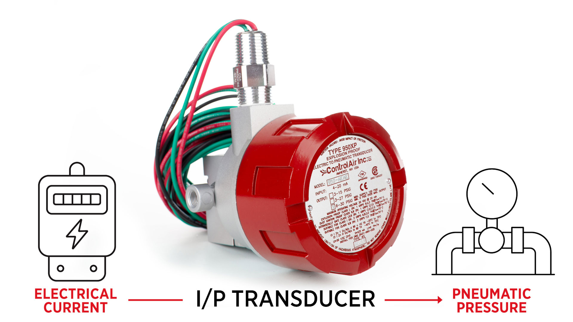
What is an I/P Transducer?
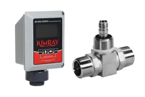
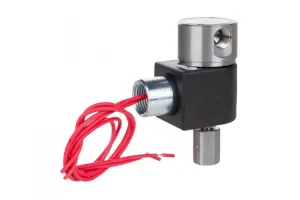
An I/P transducer translates an electric current into a pneumatic pressure.
The device receives an electrical signal, or current (I) and translates that into an output pressure (P) that is directly proportional to the current input signal.
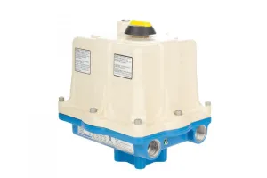
Kimray has partnered with ControlAir to offer the 950XP I/P transducer. We have two models - the YAK2 and YAK3. Both are designed for use with natural gas media, but the YAK3 is ATEX certified as well.
Calibration
Though the units are factory calibrated for direct acting operation, it is recommended to check the calibration for your specific application requirements.
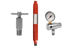
Tools Needed for Calibration:
- Process meter
- Precision screwdriver
- Gauge to monitor output pressure
- Air supply (100 psi maximum)
Pre-Installation Requirements:
There are a few important requirements to keep in mind before installation or calibration.
⚠️ The electrical input must be a 4-20 mAdc current source.
⚠️ It is recommended that shielded cable be used and that the shield be grounded to unit and earth ground.
⚠️ Your air supply must be clean, dry, and oil-free filtered to 40 microns.
⚠️ Do not apply electrical input for extended periods without supply air pressure being present.
⚠️ Reverse polarity will not damage the unit, but the unit will not operate.
⚠️ Conduit should be connected to prevent condensation from collecting in the unit.
CAUTION: The procedures demonstrated in this video are intended for general informational purposes only. Always follow your company’s safety requirements, policies, and applicable regulations when performing any maintenance or repair.
Before starting any repair or maintenance activities:
- Review and follow all DANGER, WARNING, CAUTION and NOTES found in the ControlAir Installation, Operation, and Maintenance (IOM) guide for your specific product.
- Wear all required personal protective equipment (PPE), including approved eye protection, steel toe safety shoes, and nitrile gloves to protect against exposure to chemicals and other hazardous materials.
- Failure to use appropriate PPE or follow proper procedures can result in serious injury or death.
WARNING: Before any service, be certain that the valve is fully isolated and that all pressure upstream and downstream has been relieved. Use bypass valves or fully shut off the process. Be sure that any operating or instrument gas lines have been disconnected. Never assume that a check valve is fully blocking the downstream line. Never tighten any fitting or the main connections to the regulator while there is pressure on the line.
Setup for Calibrating
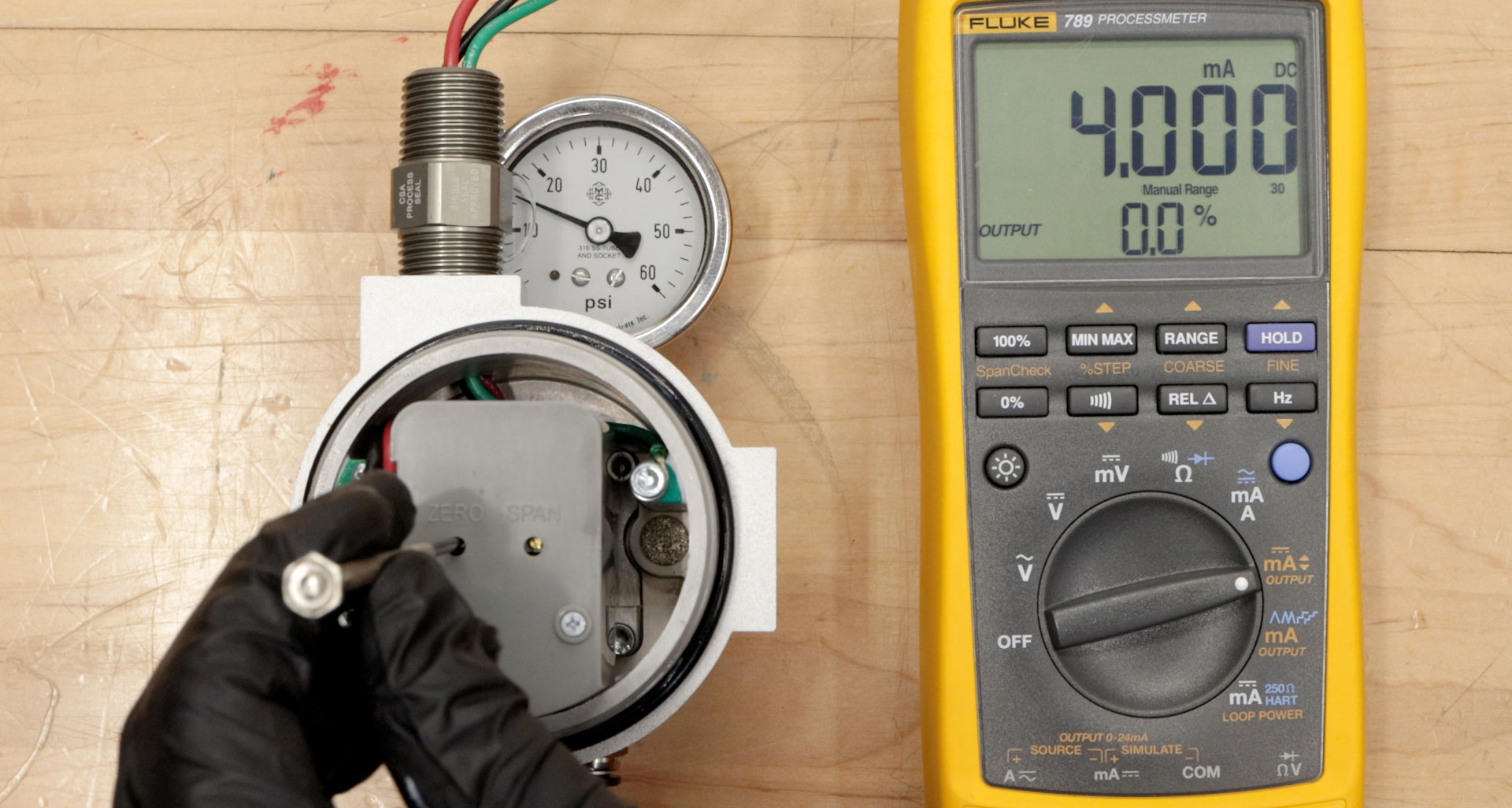
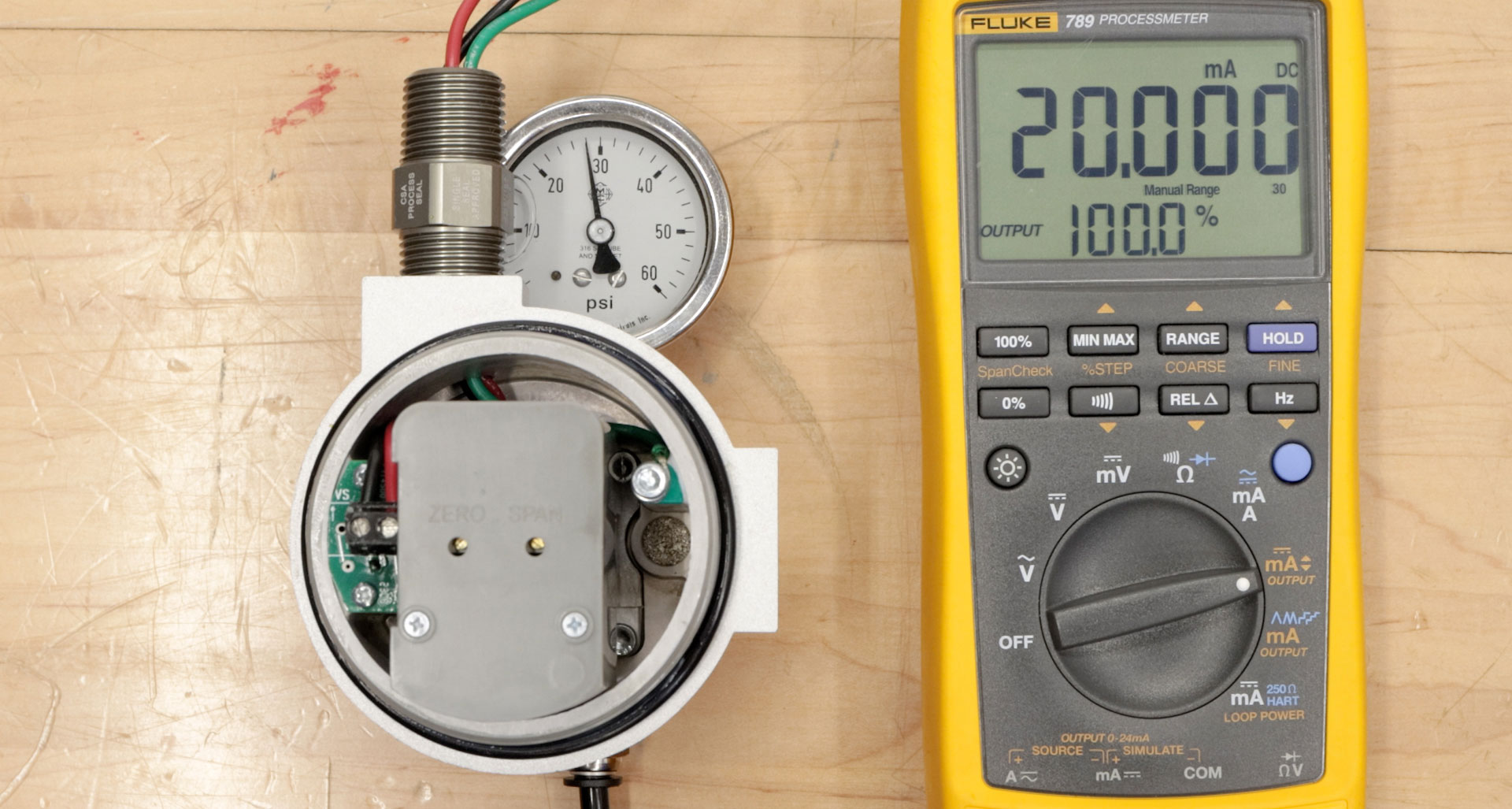
- Connect the black wire of your process meter to the black wire of the I/P unit.
- Then connect the red wire of your process meter to the red wire of the I/P unit.
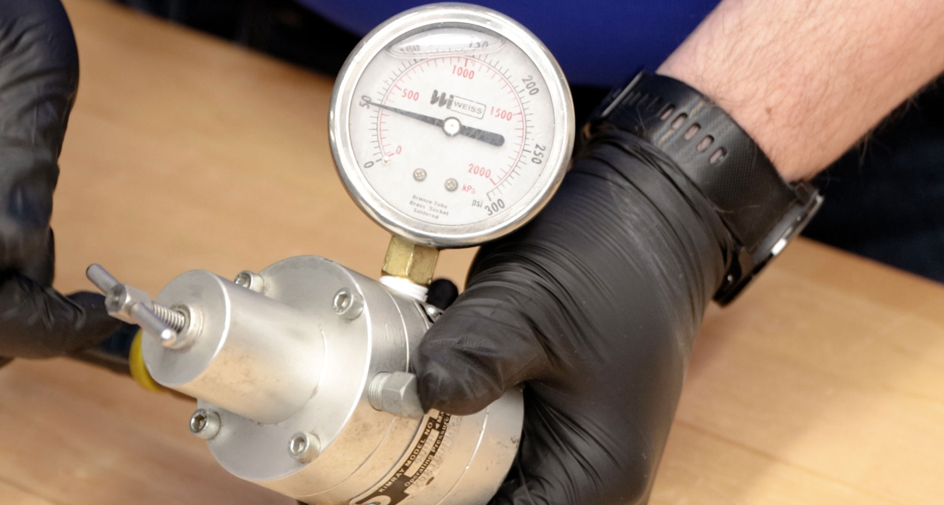
- Connect a gauge to monitor output pressure.
Connect your regulated air supply to your desired input port. This air must be regulated to no greater than 100 psi.
- Remove the explosion-proof housing from the unit.
Direct Acting Calibration
For direct acting operation, a minimum input signal corresponds to minimum output pressure. Increasing input signal results in increasing output pressure.
Apply the minimum input signal of the range being used, which would be 4mA for a 4-20mA unit.
- Regulate your supply pressure to the desired condition. For this example, we’ll be using 50 psi.
- Observe the output pressure on the gauge. Adjust the zero screw with a precision screwdriver until reaching minimum output pressure setting. For this example, we want a minimum of 10psi. Turn the zero screw clockwise to decrease and counterclockwise to increase.
Next, apply the maximum input signal of the range being used. This will be 20 mA for a 4-20mA unit.
- Now observe the output pressure. If necessary, adjust the span screw until reaching the maximum output pressure setting. In this example, we want a maximum of 30 psi.
- After setting the span, recheck the zero as we did earlier. Repeat these steps until both end points are at the required values.
NOTE: If your output pressure is not responding proportionally as expected, check the dip switch settings. We’ll go over that in the next section about calibrating for reverse acting.
Reverse (Indirect) Acting Calibration
When calibrating for reverse acting mode, the minimum input signal produces the maximum output pressure. Increasing the input signal results in decreasing the output pressure.
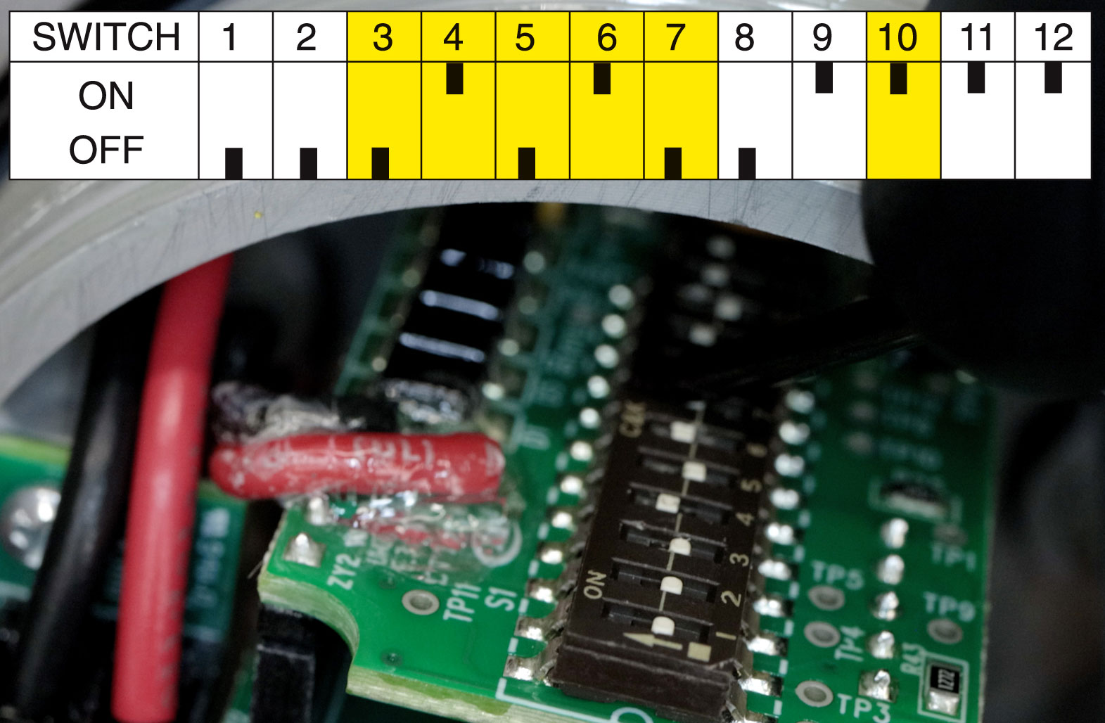
Setting the unit to operate in the reverse acting mode is done by positioning the internal electrical dip switches.
– Do not touch any components on circuit board except dip switches.
– Do not reverse the input leads.
– The transducer fails in direct mode regardless of operating mode selected.
- Remove the two screws on the plastic cover to access the circuit board.
Position the dip switches as illustrated. You will only change the switch settings on switches 3, 4, 5, 6, 7 & 10.
- Replace the plastic cover.
- Set the input signal to the minimum value being used (4mA).
- Turn the zero screw to set the maximum output pressure. In reverse acting mode, the effect of turning the span screw is the opposite of direct acting mode. Turn clockwise to decrease and counterclockwise to increase. We will be setting this to 30 psi.
- Next, set the span by applying the maximum input signal. Turn the span screw to set the minimum output pressure–counterclockwise to decrease and clockwise to increase.
- It may be necessary to repeat these steps until both end points are at the desired values.
- Finish by replacing the explosion-proof cover.
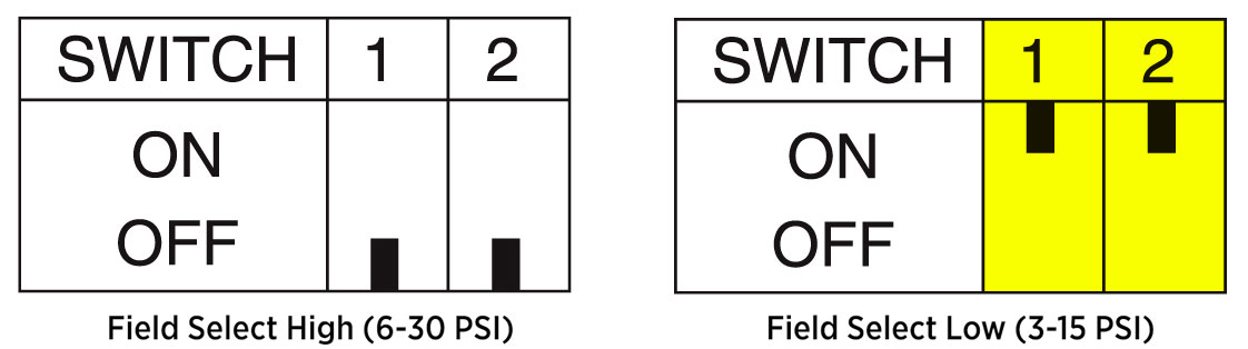
Field Selectable Calibration (Optional)
If you’re wanting to control a smaller range with a low-end pressure less than 6 psi, you can switch your unit to the low setting by adjusting the dip switches accordingly.
Then, follow the same calibration steps above.
That completes the calibration process for the I/P Transducer. Reach out to our Kimray support team if you have any questions about this process or automation and electric products.