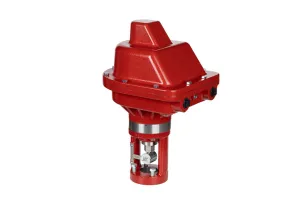
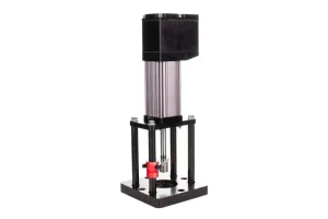
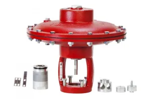
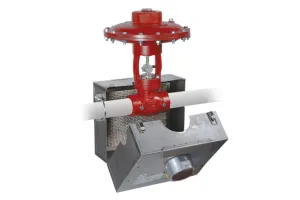
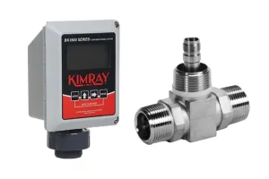
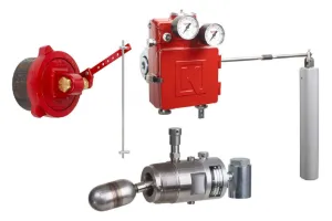
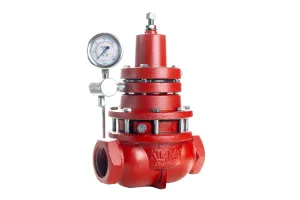
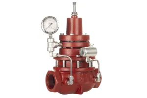
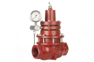
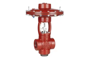
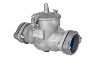
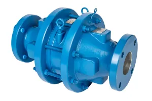
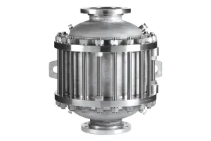
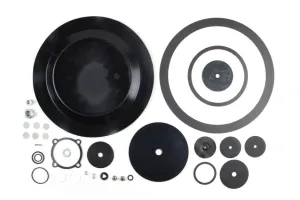
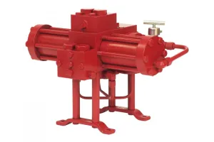
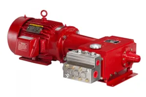
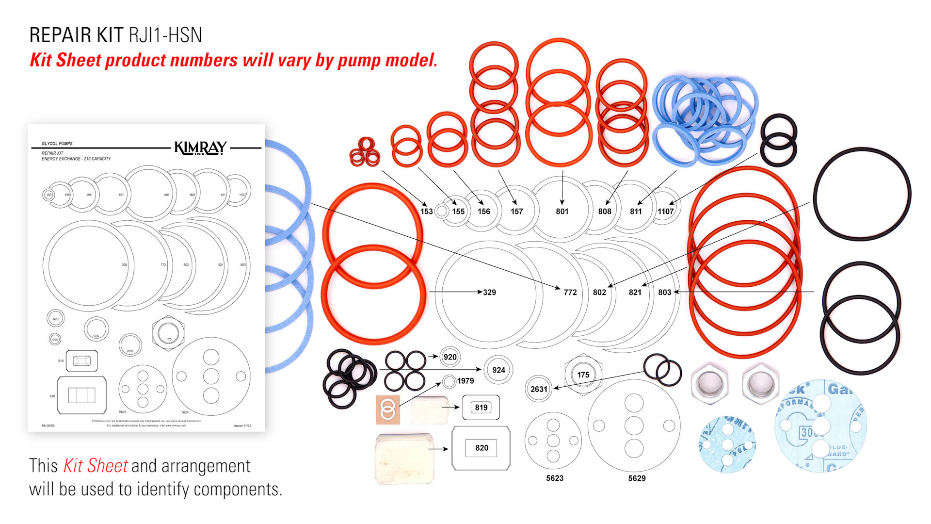
Kimray’s Energy Exchange Glycol Pump is a durable, low-maintenance solution for recirculation of glycol in your dehydration system. With a repair kit and this guide, you can safely and effectively maintain your glycol pump.
Before any service, be certain that the valve is fully isolated and that all pressure upstream and downstream has been relieved. Use bypass valves or fully shut off the process. Be sure that any operating or instrument gas lines have been disconnected.
Consult your company’s safety guidelines and requirements. Follow all regulations and wear all necessary PPE.
How to Disassemble an Energy Exchange Glycol Pump
- Remove any plugs from your suction or discharge blocks.
- While standing to the side of the glycol pump just in case there’s any discharge, slowly open your needle valves to relieve any trapped pressure.
- Remove your check valve caps and the O-rings.
- Use needle-nose pliers to remove the check valves.
- Use a pick to remove the upper and lower O-rings from all four check valves.
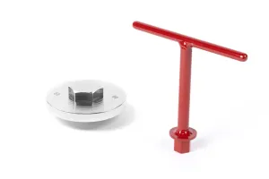
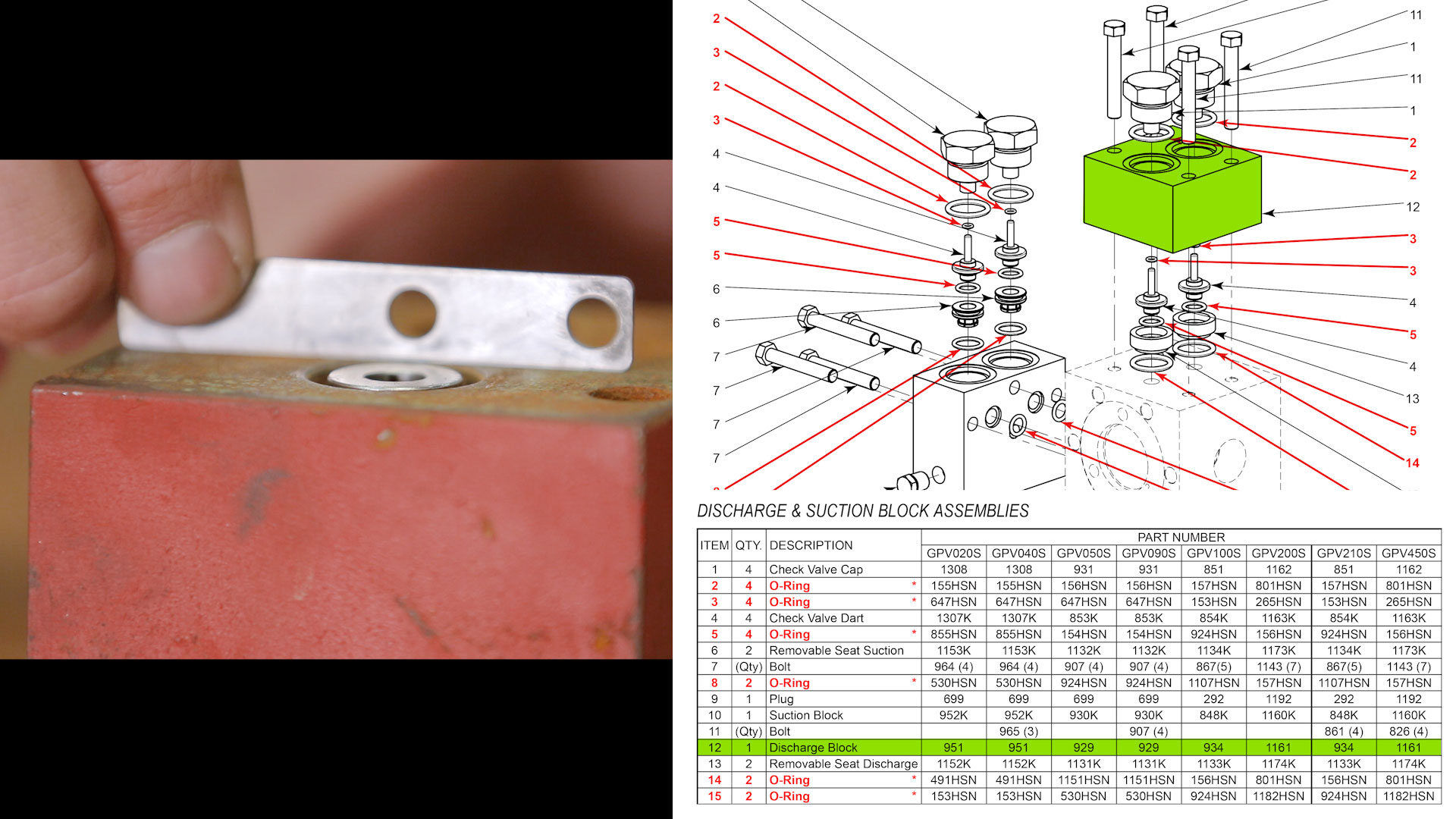
- Use the seat puller and a wrench to remove the suction block seats.
- Remove the O-rings from the suction block seats.
- Remove the discharge block from the main piston body.
- Use the seat insert tool and mallet to remove the discharge seats from the discharge block.
- Remove the O-ring from both discharge seats.
- Remove the suction block from the main piston body.
- Remove the (2) O-rings from the backside of the suction block.
- Flip the glycol pump upside down and loosen the fitting from the pilot piston discharge tubing.
- Remove the tubing from the main piston valve housing.
- Remove the pilot piston discharge tubing.
- Remove the legs closest to the main piston valve housing.
- Loosen the bolts to remove the main piston valve housing
- Remove the O-ring from the main piston valve housing.
- Use needle-nose pliers to remove the Main Piston "D" slide.
- Put the main piston valve housing in a vice and remove the "D" slide guides.
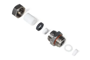
- Use two wrenches to loosen both ends of the needle valve assembly tubing. To prevent the fitting from breaking, hold the fitting elbow with one wrench and use the other to loosen the fitting cap. [Repeat on both sides]
- Replace the legs and flip the pump right-side up.
- Loosen the bolts on the pilot piston valve housing.
- Remove the control tubing.
- Remove the O-ring from the pilot piston valve housing.
- Turn the tubing elbow to protect the threads before loosening the bolts on the cylinder head.
- Slide off the cylinder head and remove the O-ring.
- Then remove the cylinder. [Repeat on both sides.]
- Use a wrench to hold the piston rod in place and loosen the nut from the other side of the piston.
- Slide off the piston retainer and remove the O-ring and (2) back-ups.
- Remove the O-ring from the piston retainer groove.
- Remove the piston rod gland from the body.
- Then remove the O-ring from the piston rod gland.
- Flip the pilot piston gland over and remove the (2) O-rings located in the communicating hole grooves. [Repeat on both sides.]
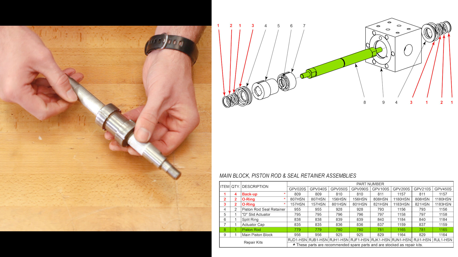
- Work the piston rod from side to side to jar loose the piston rod seal retainers.
- Remove the O-ring and backup from the piston rod seal retainer. [Repeat on both sides.]
- Slide out the piston rod.
- Loosen the bolts and remove the pilot piston caps.
- Remove the backup from each of the pilot piston caps.
- Tap the pilot piston with a mallet and slide it out of the glycol pump.
- If the piston bearings don’t come out on their own, put the Kimray seal retainer tool into the pilot piston hole and tap with a mallet to remove them.
- Remove the O-Ring and back-up from both pilot piston bearings.
- Place the pilot piston valve housing in a vice.
- Remove the needle valve handles with an hex wrench. If the handle is rusted, the head on the hex screw may break off. If this occurs, use the handle of a wrench to break it off. It will then need to be replaced.
- Loosen the needle valve caps, and then remove the needle valve bonnet.
- Remove the needle valve cap and unthread the stem.
- Remove the "D" slide guides.
- Remove the backup and O-ring from each needle valve bonnet.
Now that the pump is fully disassembled, run your parts through a parts washer. If you don’t have access to a washer, get each part as clean as possible.
How to Inspect an Energy Exchange Glycol Pump
Piston Rod
- Check your piston rod for any scratches or scoring. If you can feel the scoring with your fingernail, the piston rod needs to be replaced. If it only has light scratches, they can often be smoothed out with 220-grit or finer Emery cloth.
- Check your piston rod for any uneven wear or ripples that you might feel on the surface.
Piston
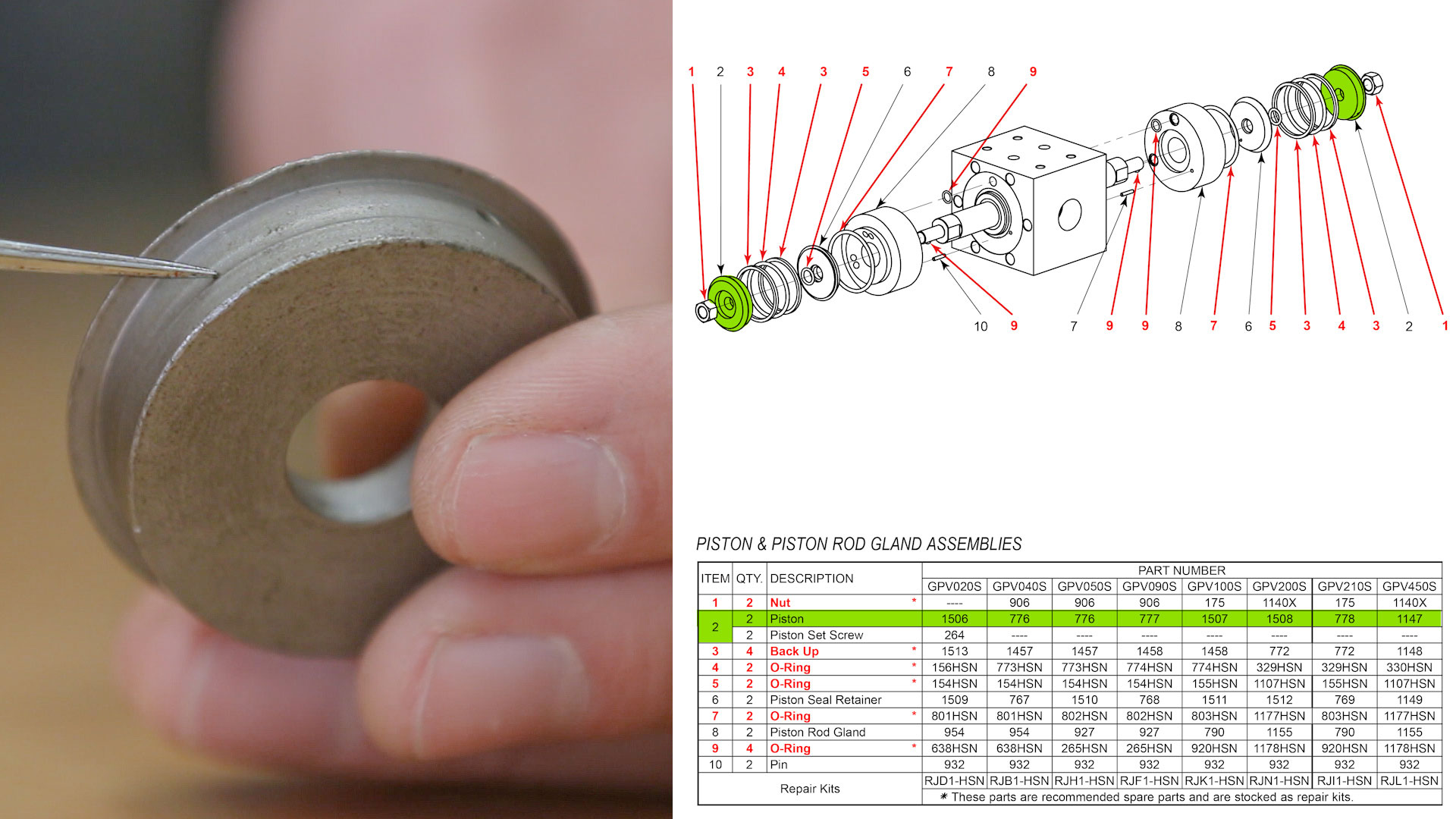
- Check the outside surface of your piston where the O-ring and backups are placed. If you see a groove where that O-ring was setting, it will need to be replaced.
Piston Seal Retainers (x2)

- Inspect your piston rod seal retainer for any groove where the O-ring used to set. These are very critical since a lot of glycol pump failures occur when wet and dry glycol mix through this area whenever it’s compromised. If the surface where the o-ring set shows wear or ripple, it will need to be replaced.
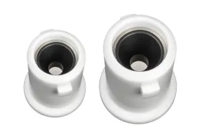
Piston Rod Gland (x2)

- The piston rod gland will need to be replaced if the surface where the backup sits shows any groove, if excessive wash outs are present, or if the communicating holes are damaged. If this surface gets damaged, it could result in leaks between the body and the gland.
Cylinders (x2)
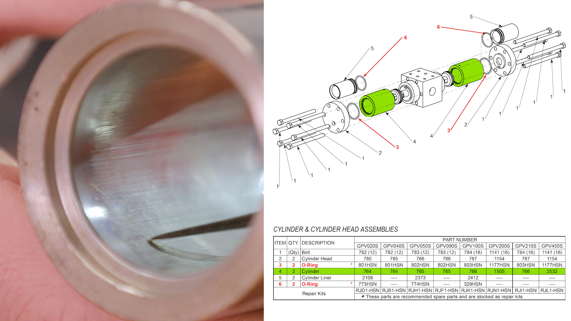
- If you can feel the scoring on the inside of the cylinder, it will need to be replaced.
- The cylinder will also need to be replaced if you can fill any ripples at the end of the stroke area.
Pilot Piston
- Check your pilot piston for any scratches, uneven wear, or ripples. If you can feel the scratches or ripples with your finger, it will need to be replaced. If the scratches are very light, they can be removed with 220-grit or finer Emery cloth.
Pilot Piston Bearing
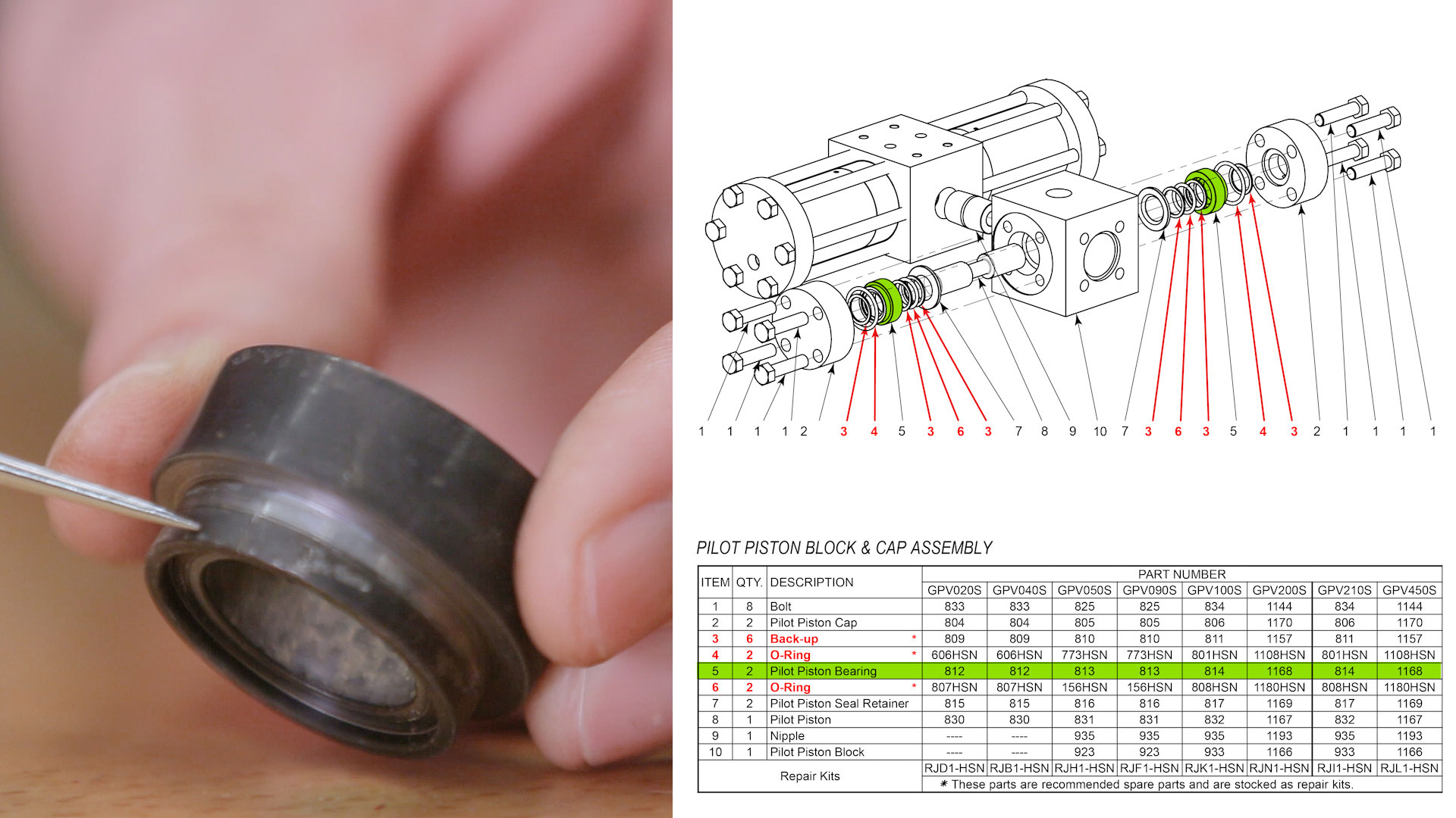
- If there’s a groove on the O-ring surface on the outside or on the inside, it will need to be replaced.
Check Valve Caps (x4)

- The check valve caps will need to be replaced if the clearance between the cap and the check valve is too much. Take a check valve and slide it into the cap and check for side-to-side play. Make sure that the check valve goes in and out freely. If there is interference between the cap and the check valve, clean the check valve cap with the appropriate-sized reamer.
- Make sure the communicating hole is clear. This can be done with an air nozzle or an awl.
Check Valves Darts (x4)
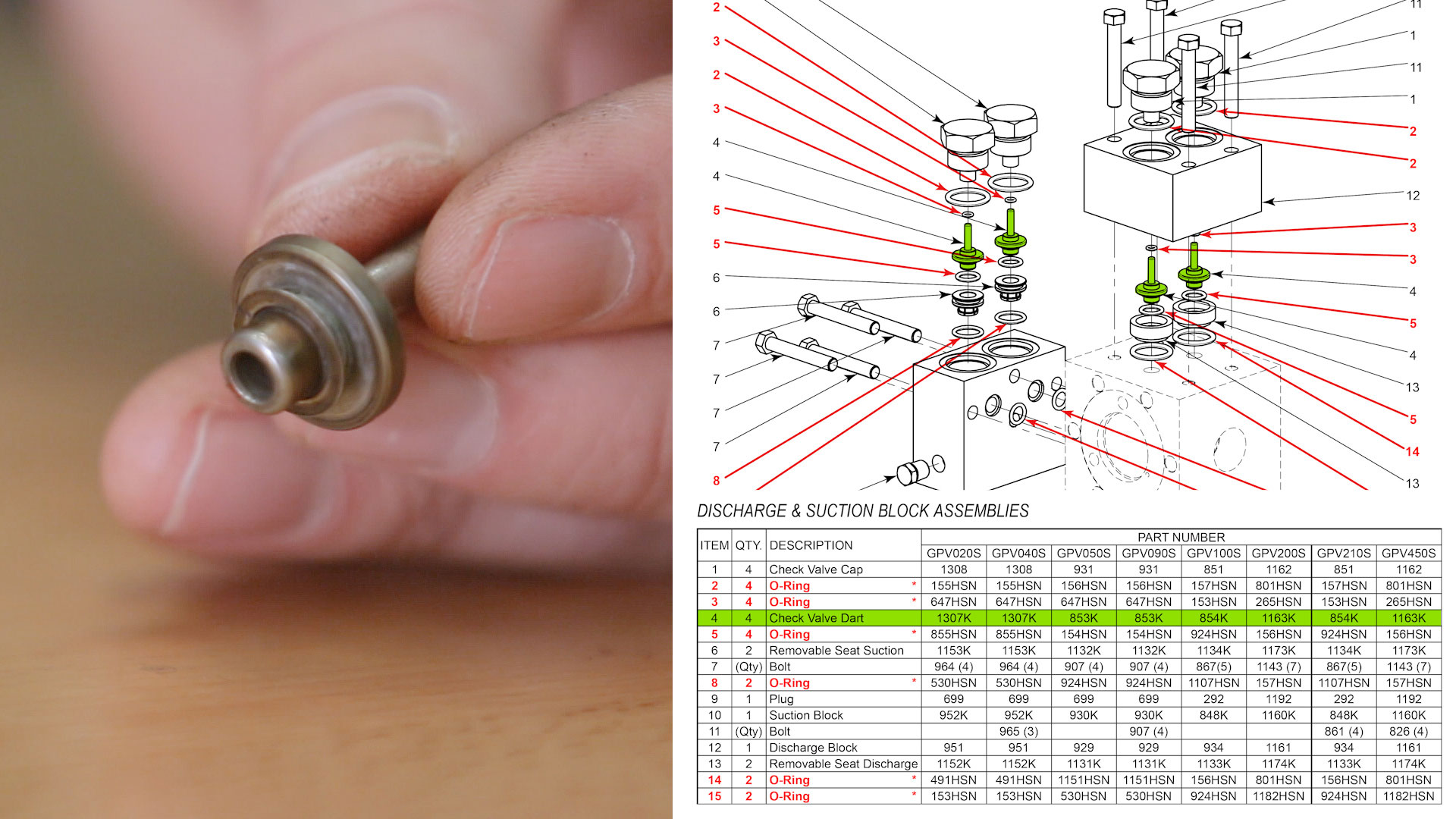
- The check valve darts will need to be replaced if there’s any ripple on the stem or any damage to the o-ring ledge.
Suction Block
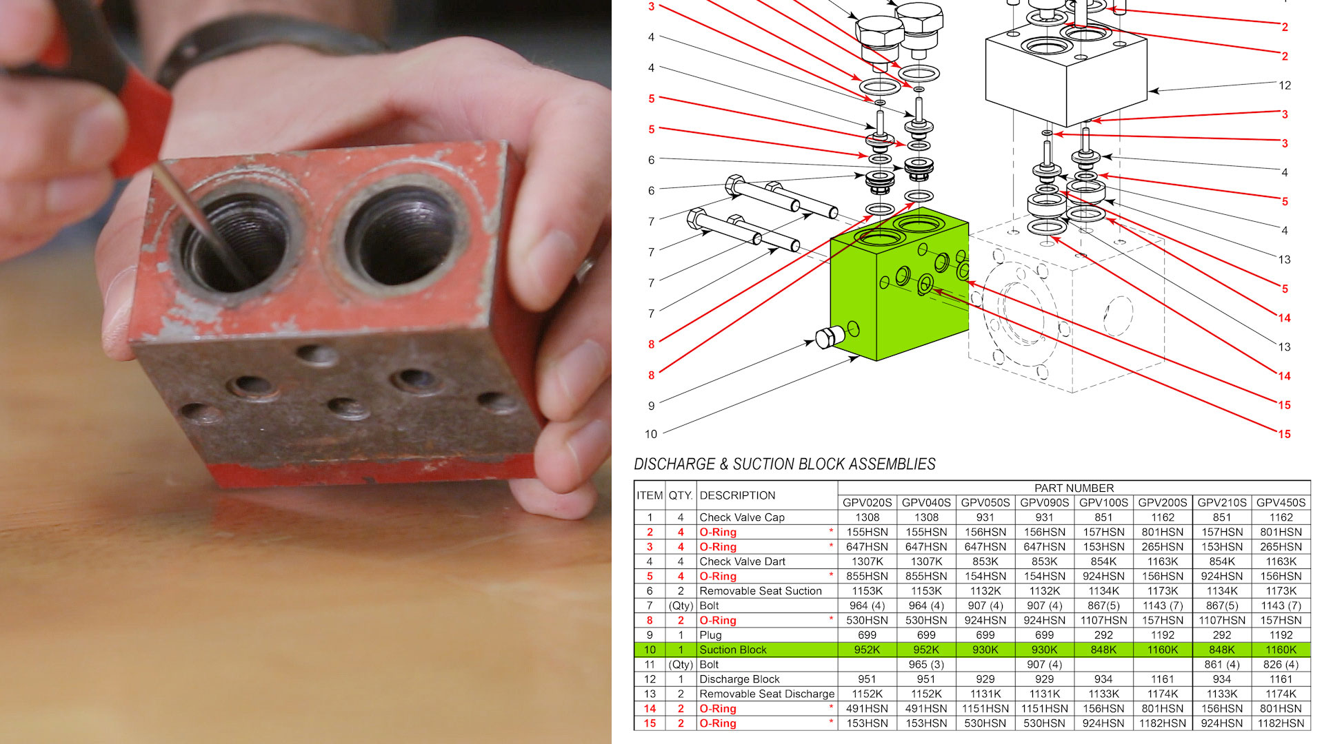
- If the O-ring surface of the wall has grooves or excessive wear, it will need to be replaced.
Discharge Block
- Put the seats in the discharge block, then take a straight edge and lay it across the seats. They should be close to flush with the block surface. If the seats are sitting too low, it may cause a leak between the block and the body.
- Check for wear on the top of the body due to the seat’s impact. Sometimes after a continuous hammering of the check valves on the discharge seats, the seats can wear on the body surface.
Removable Seat Suction (x2) and Removable Seat Discharge (x2)
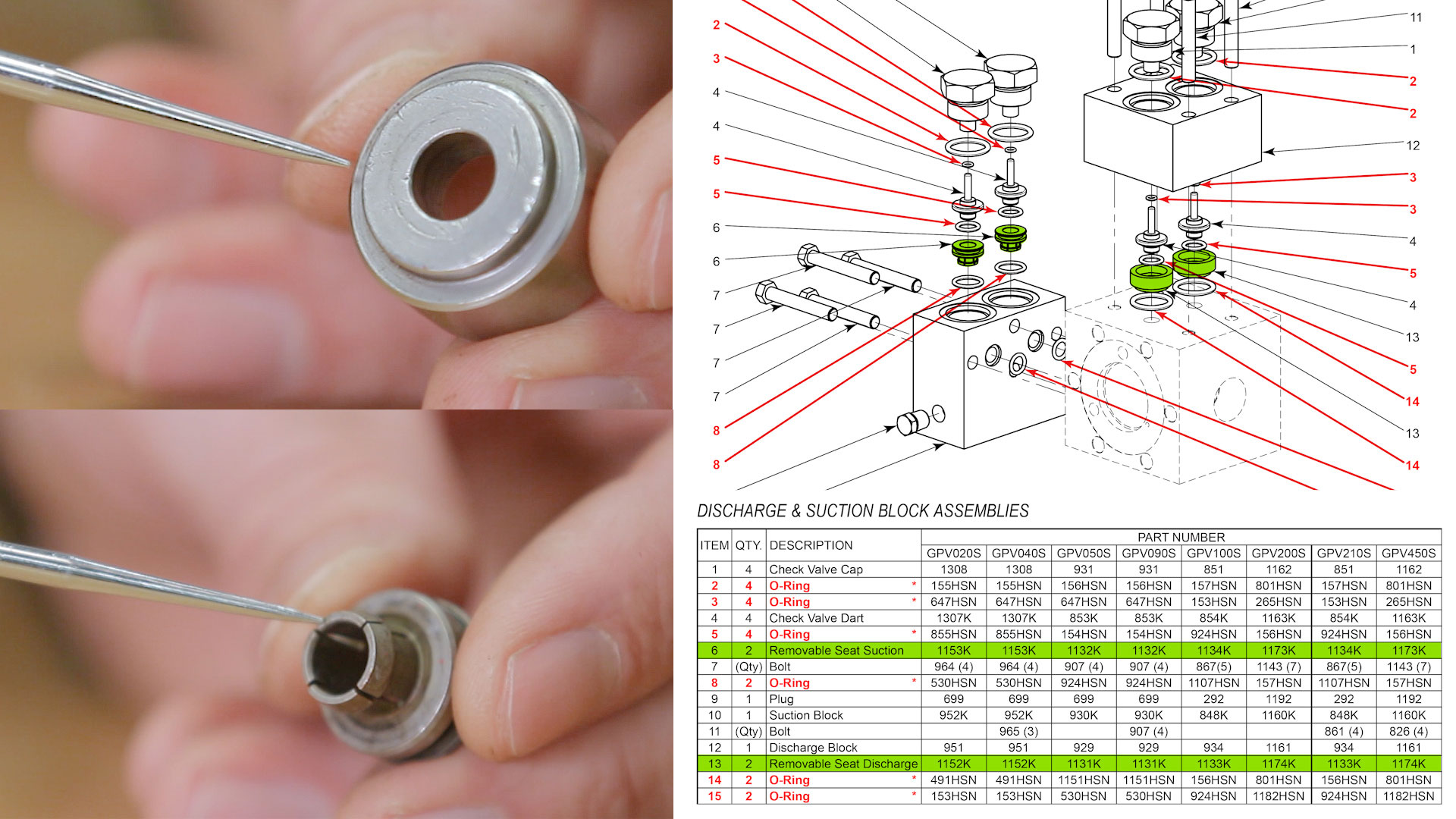
- They’ll need to be replaced if there is excessive wear on the seats, if the segments of the collet on the suction seat are bent, or if the check valve doesn’t fit freely in the seats.
Port Plate Surfaces (old style pumps only)
- If you are rebuilding one of the newer style glycol pumps, the port plates on the main piston housing and the pilot piston housing will be replaceable. If you have the older style glycol pump, the surfaces on the port plates will need to be refinished. To do this, use 220-grit sandpaper to buff out any gouges or deep scratches on the face of the port plate. Apply pressure, keeping the port plate even on a flat surface. Go back and forth three to five times and make sure that all of the scratches have disappeared.
- Rotate the piston housing 90°. Lightly press and sand one more time. This will show if there are any more deep scratches to be sanded.
- After sanding the port plates, use the air nozzle to make sure the inside orifices are all clear. Repeat this process for the main piston housing.
How to Reassemble an Energy Exchange Glycol Pump
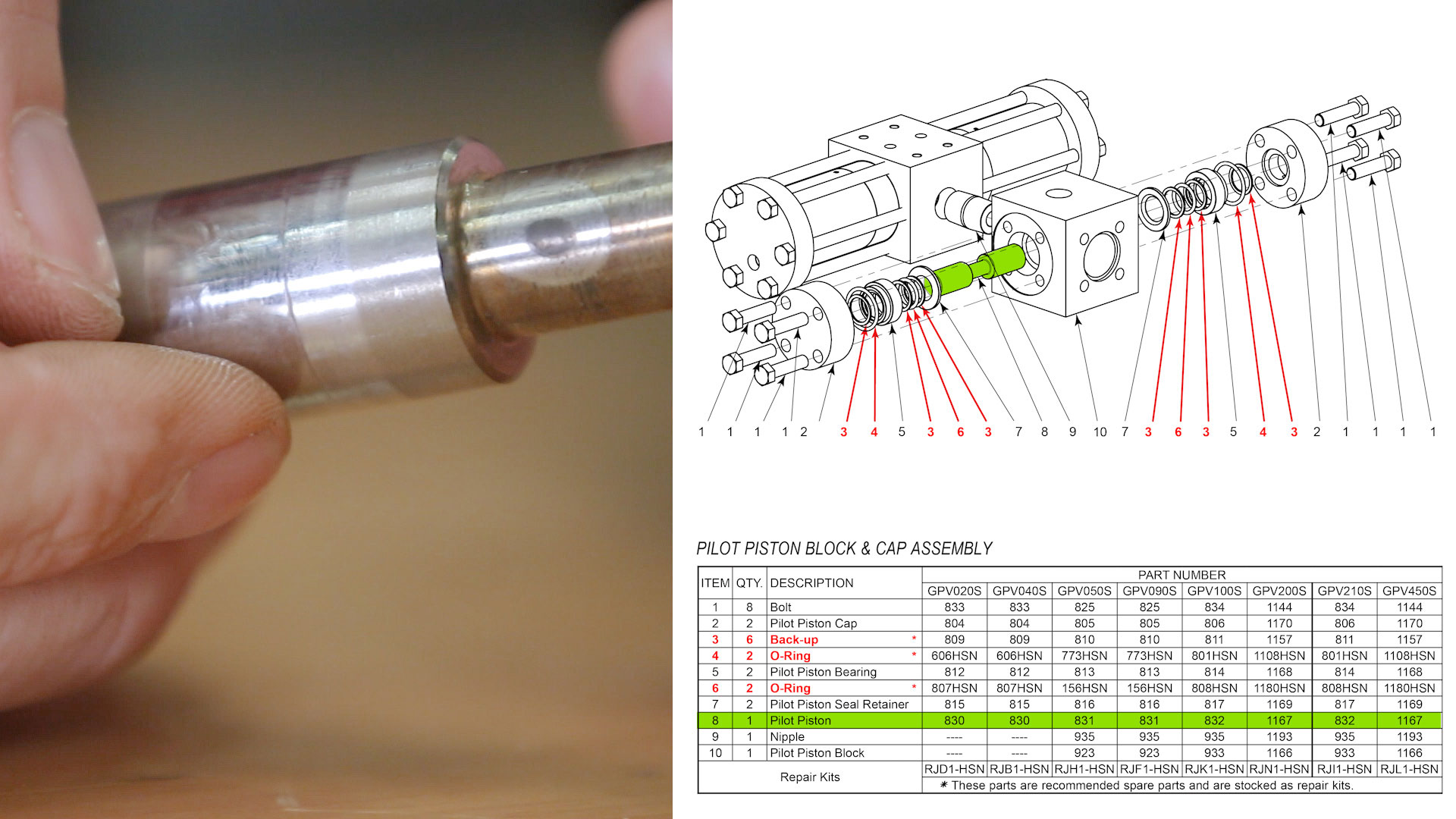
Piston Pilot Block & Cap Assembly
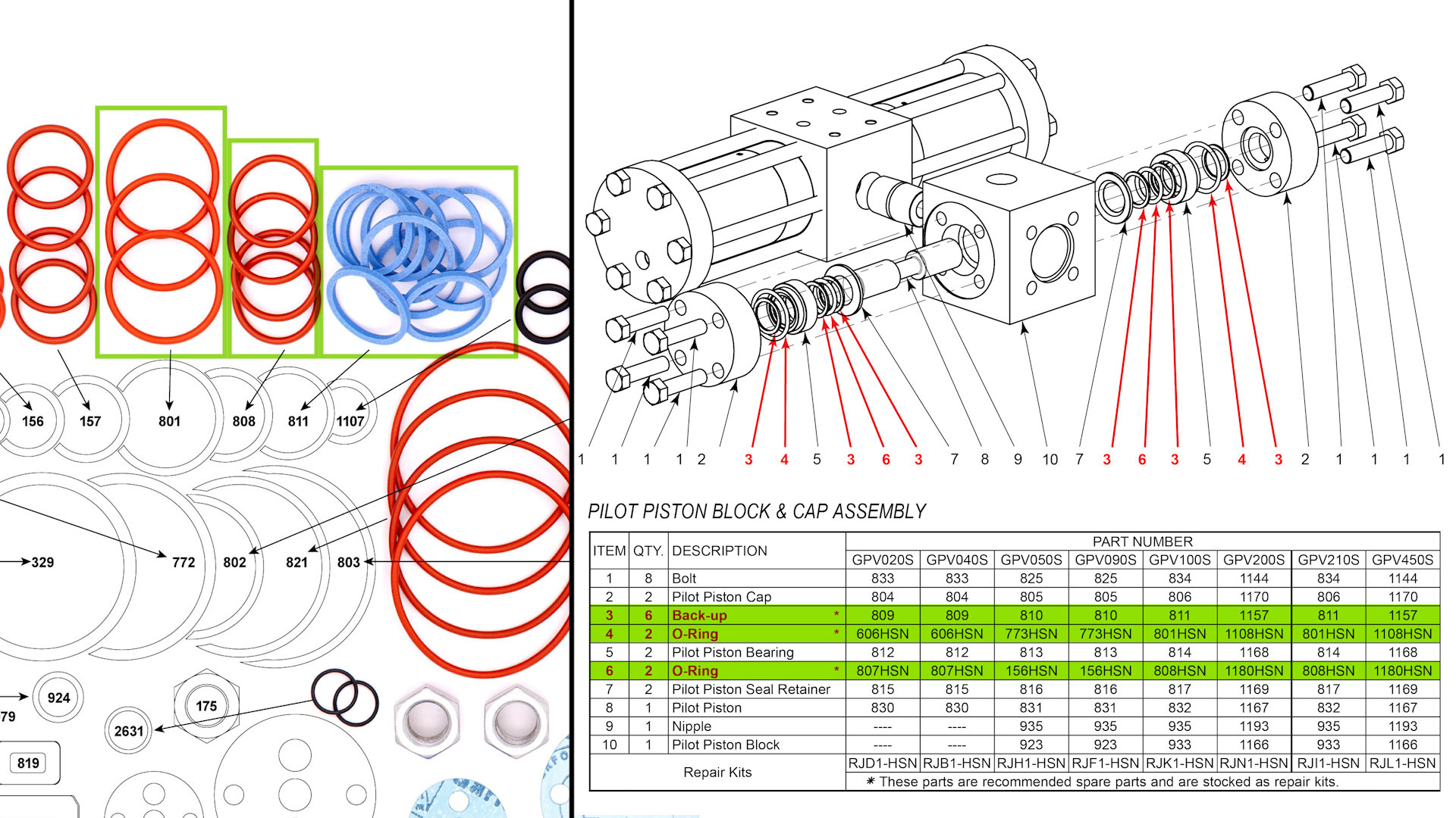
- Insert the pilot piston seal retainer with the beveled side facing in on both sides of the glycol pump. Push them in until you feel a mechanical stop.
- Reassemble the pilot piston bearing using the (2) O-rings and (3) back-ups.
- Use a light-gravity motor oil to generously lubricate all of your O-rings and back-ups during assembly.
- Insert the pilot piston bearing assembly into the pilot piston body.
- Repeat this assembly for the second pilot seat retainer.
- Place the pilot piston cap over the bearings and seat the O-rings in place. This prevents the O-rings from getting pinched later when you install the pilot piston caps.
- Attach one of the pilot piston caps to the glycol pump body.
- Use oil to lubricate the piston rod and then insert it into the main piston body. Push it until it’s flush with the pilot piston bearing.
- Then attach the second pilot piston cap.
- Use a screwdriver to move the pilot piston back and forth, making sure that it moves freely. If the pilot piston is stuck, loosen the bolts on the pilot piston cap until it moves freely and then tighten the bolts and check it again.
- Install the main piston and make sure that it moves freely through the glycol pump body.
Piston & Piston Rod Gland Assemblies

- Insert (2) O-rings in the communicating hole grooves on the piston rod gland.
- Place the larger O-ring on the opposite side of the piston rod gland.
Main Block, Piston Rod & Seal Retainer Assemblies
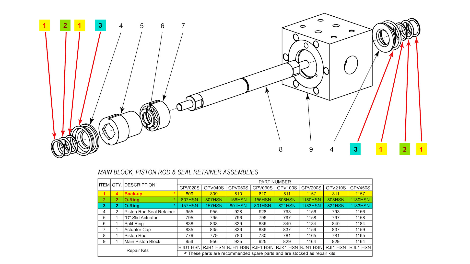
- Insert a back-up, O-ring, and second back-up into both of the piston rod seal retainers.
- Place another O-ring around the outside of the piston rod seal retainers.
- Lubricate the O-rings and back-ups on the seal retainers with oil, then install them into the piston rod gland.
- Lubricate the piston rod with oil to prevent damaging the seal retainer O-rings.
- Make sure that the index pins are in the body, then slide the gland and the seal retainer assembly onto the piston rod and align the index pin with the hole on the gland. [Repeat these steps on both sides.]
Piston & Piston Rod Gland Assemblies
- Insert an O-ring inside the piston seal retainer.
- Place a back-up, O-ring, and second backup around the outside of the piston.
- Place the piston seal retainer on top of the piston assembly.
- Lubricate the O-rings and backups with oil and place the piston seal retainer and the piston assembly onto the piston rod.
- Thread on the lock nut with the bevel side facing out and tighten it while holding the piston rod still with a wrench on the backside of the piston. Make sure that the gland doesn’t move out of place when tightening the lock nut. [Repeat this step on both sides.]
- Lubricate the inside of the cylinder walls with oil.
- Slide the cylinders under the pistons.
Cylinder & Cylinder Head Assemblies
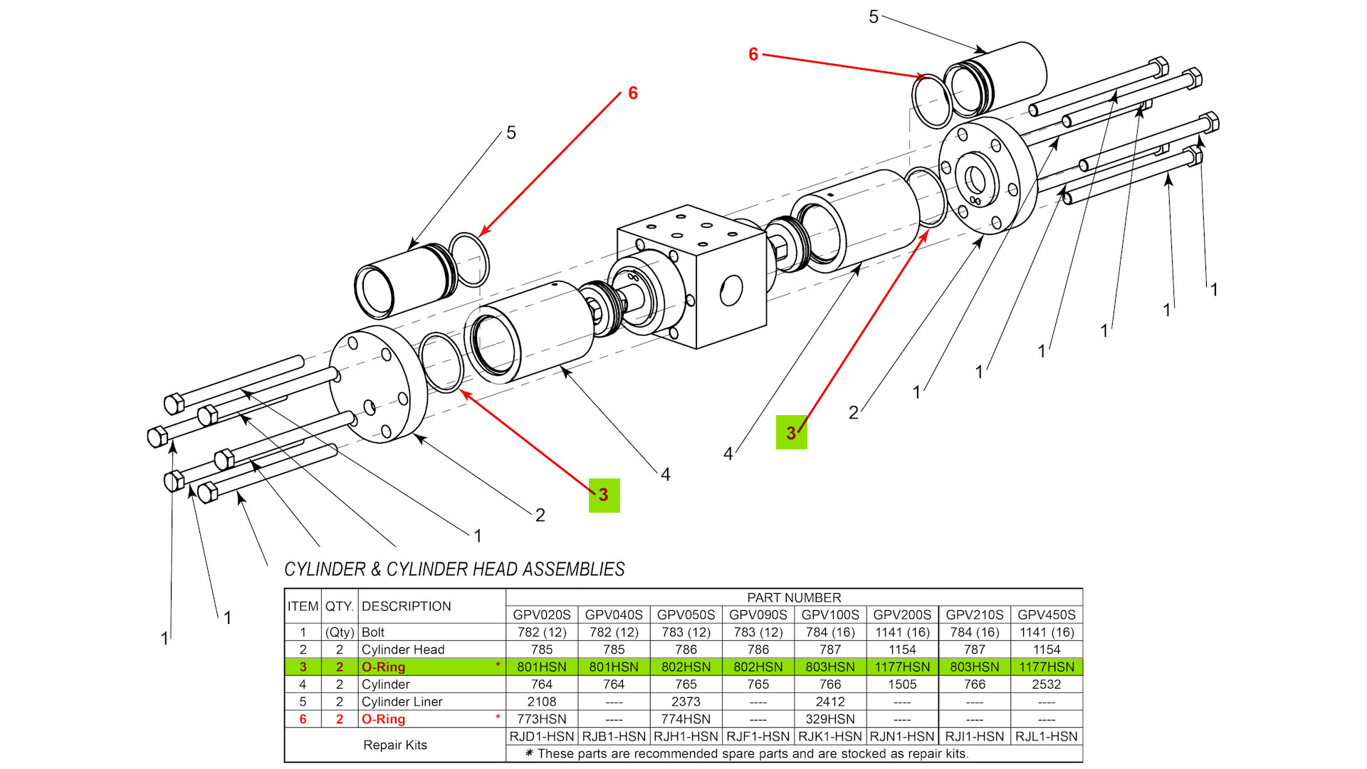
- Install the cylinder head O-rings and lubricate them with oil.
- Place the bolts into the cylinder head and mount it on the cylinder making sure that the tubing fitting is in the correct place.
- Tighten the bolts in a star pattern.
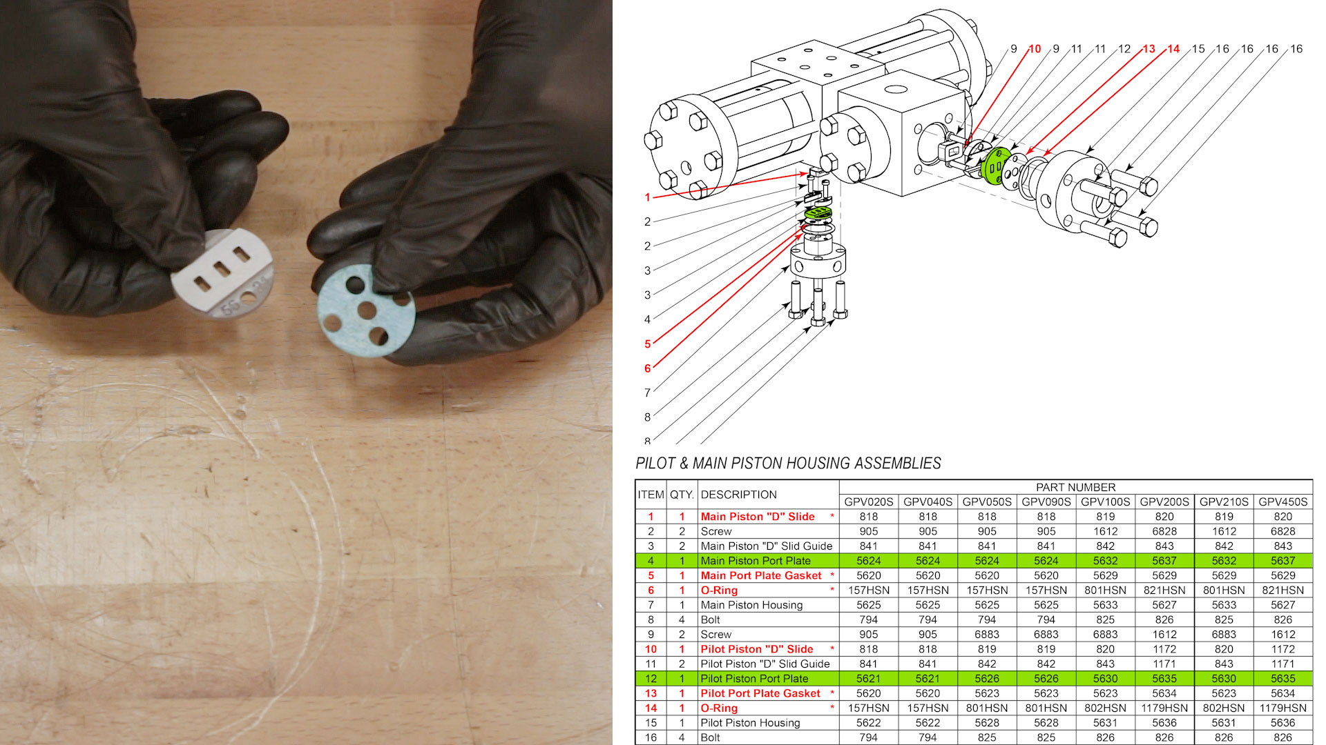
Pilot & Main Piston Housing Assemblies, Part 1

- In newer style pumps you’ll have gaskets that will go underneath the removable port plates.
- Place an O-ring on the main piston valve housing.
- Place an O-ring on the pilot piston valve housing.
- Install the "D" slide guides on both housings.
Pilot & Main Piston Housing Assemblies, Part 2
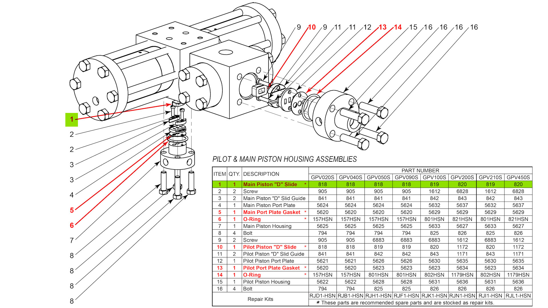
- Remove the legs closest to the main piston valve housing so that there will be room to tighten the bolts on the pilot piston housing.
- Coat the "D" slide in oil and place it on the main piston valve housing. The oil will keep it in place while you install it in the pump body.
- Insert the bolts that hold the pilot piston valve housing in place.
- Reinstall the legs closest to the main piston valve housing.
- Install the tubing. Start with the shorter of the two U-shaped tubes with one end on the main piston valve housing and the other end on the pilot piston cap. Hand tighten the fitting caps so that they don’t cross thread and then tighten them down fully.
- Install the longer U-shaped tube on the other main piston valve housing fitting and the pilot piston cap.
Pilot & Main Piston Housing Assemblies, Part 3
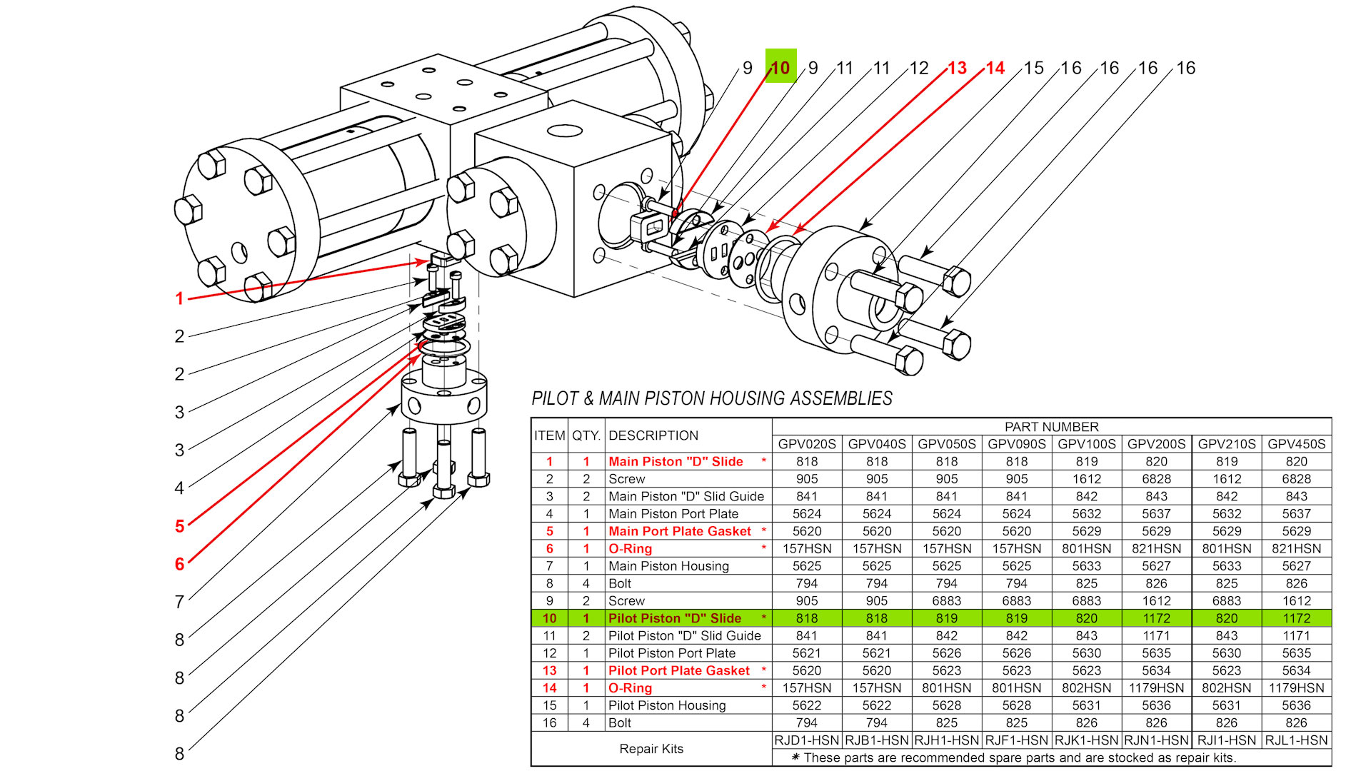
- Coat the "D" slide in oil and place it on the pilot piston valve housing
- Lubricate the O-ring around the valve housing.
- Insert the pilot piston valve housing into the pump body
- Rotate it slightly to be able to install your pilot piston tubing.
- Hand start the pilot piston tubing and then bolt down the pilot piston valve housing.
- Tighten down the pilot piston tubing and then stand the pump up on its legs.
- Hand start the L-shaped tubing on the needle valve side and use a wrench to move the tubing elbow into position.
- Push the tubing into place and tighten the fittings. [Repeat for the other side.
Discharge & Suction Block Assemblies
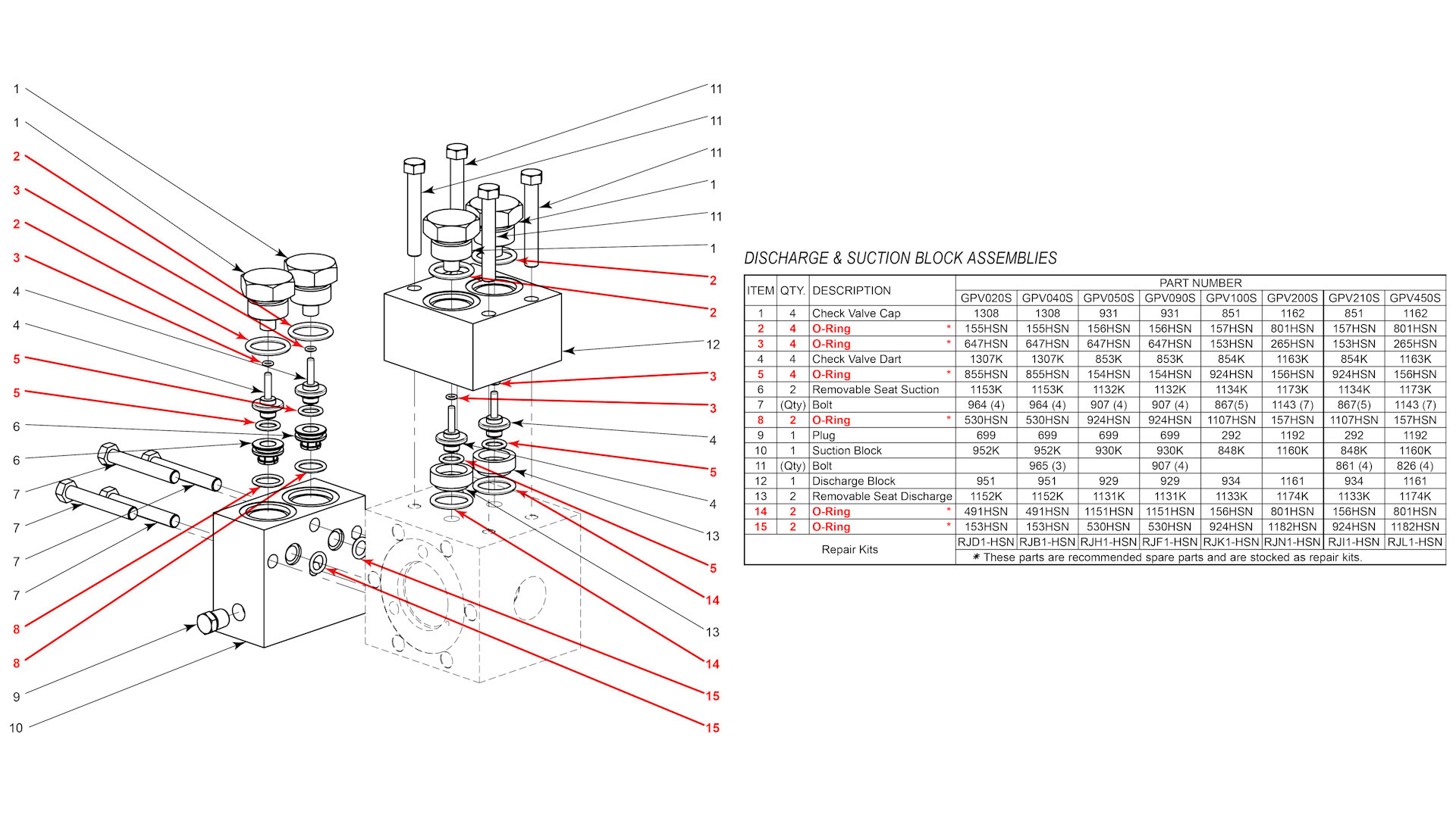
- Insert the discharge seats into the block.
- Place the O-rings on top of the discharge seats.
- Place the upper O-ring and lower O-ring on both check valves.
- Lubricate the check valves with oil and insert them into the block.
- Put an O-ring on both check valve caps and install them onto the discharge block.
- Verify that the check valves are moving freely by shaking the discharge block. If they are installed properly, you will be able to hear them moving back and forth.
- Put the O-rings onto the suction seats and lubricate them with oil
- Install the suction seats into the suction block with the suction seat tool. Tap the seat into place, being careful not to shear the O-ring (you should feel a little bit of resistance).
- Place the upper O-ring and lower O-ring on the check valves.
- Lubricate the check valves with oil and insert them into the block.
- Place the O-rings on the check valve caps and install them into the suction block.
- Tighten the check valve caps by hand with a crescent wrench so that you don’t over tighten them.
- Verify that the check valves are moving freely by shaking the suction block. You should be able to hear them moving back and forth.
- Place the (2) O-rings on the back of the suction block.
- Bolt the discharge and the suction blocks to the pump body.
Needle Valves
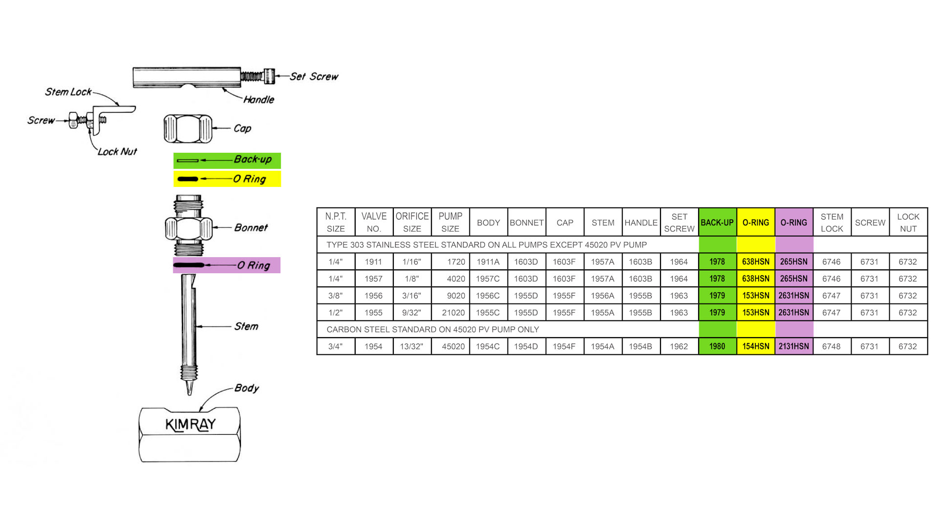
- Thread the needle valve stems into the needle valve housing.
- Place the O-rings and back-ups around the stem. The new style glycol pump has a groove in the needle valve body for an O-ring. If this groove isn’t there, do not use the O-ring provided in the repair kit.
- Thread the needle valve assembly into the control valve housing. [Repeat steps for the other needle valve.]
- Install the valve covers and attach the needle valve handles.
Congratulations! That concludes the repair of the Kimray Energy Exchange Glycol Pump.
If you have any questions about your glycol pump or need any information on the Kimray tools used in this video, reach out to your local Kimray store or authorized distributor.