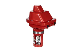
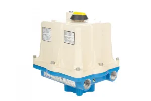
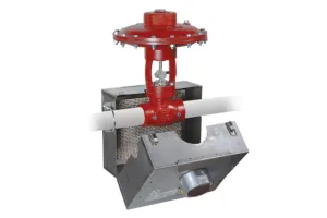


The Tritex II Electric Actuator can be used to provide electric control on any open-close or modulating application.
In this video, Alex shows you how to set it up with a 4-20 mA signal for your RTU, Scada system, or the Kimray Electric Pilot.
What You’ll Need
- A Tritex II Electric Actuator
- A laptop with Windows operating system
- Communication Cable
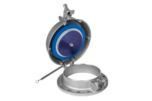
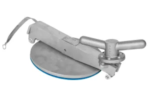
- A mounting bracket and corresponding valve mount
- 3/8” wrench
- 7/16” wrench
- Phillips-head screwdriver
- 12-Gauge wire
- Loctite
- Software from Exlar and a windows driver installed on your laptop. (Requires Windows OS)
How to Install the Tritex II Electric Actuator
Before installing the wiring, you’ll need to connect the mounting bracket to the valve, then connect the actuator to the bracket.
Next, slide the anti-rotate device onto the shaft of the actuator and apply Loctite to the threaded shaft end of the coupling block adaptor and tighten.
How to Wire the Tritex II Electric Actuator
Now install the wiring. We recommend a 12-guage wire for power.
- Take 12-48 volts DC to the Bus and common terminals.
- Then, put a jumper between the bus terminal and logic terminal.
- Wire the Inputs to J5 Terminal pin 1 (labeled AI+) and pin 2 (labeled AI-). If you want position feedback, they are wired to J5 terminal, pins 3 (labeled AO+) and 4 (labeled AO-).
How to Program the Tritex II Electric Actuator
- Using your USB-to-M8 communications cable, establish a physical connection between your laptop and the front of the actuator drive housing.
- Launch the Expert Software program and create a new template.
- Select file > New > Application.
- Choose “DC 48V Tritex II.”
- Select “IA4 Option Board.”
- Select “Generic, under the application template.
- Enter a name for the application (your site name, well pad number or valve description) and an application author and description, if you’d like.
- Click “OK.”
Establish Communication to the Actuator
- Select View > Network Communications Manager.
- Choose “Remove Network.”
- Select “Add Network.”
- Use the default setting “ModbusRTU” for the type of network to be created.
- On the next pop-up, leave all general settings as default, but open the RS485 Serial Tab.
- On the drop down menu for the Communications Port Name, select the appropriate com port for your PC.
- Click “OK.”
- Select “Scan Network” (the status should now show “connected”).
- Close the network manager window.
Read Parameters from the Drive and Adjust the User Units
- Press the “Up Arrow” button, located on the menu bar, to read the parameters from the drive/actuator to the PC. You should see lights flickering on the USB as the PC is uploading parameters from the drive.
- Adjust the user units by expanding the setup tree and selecting “user units.”
- Select “Apply.”
Couple the Actuator to the Valve and Define Home
This step is dependent on the status of the Actuator. This can be viewed in the status bar at the bottom of the software home page.
On the Input Function Control Window on the right side of the screen:
- Select “Enable Maintained.”
- Select “Define Home” and temporarily call this position home.
- Use “Jog+” or “Jog-” to move the actuator up and down in order to attach the coupler.
- Select “Reset Faults” if the current limit is reached.
Configure the system setup
- On the left side of the screen select “System Setup” under the directory tree.
- Don’t make any changes on the Comms Faults tab or the Position Window tab.
Options Tab
- Check “Auto Enable on Startup.”
- Check “Allow Jog override of Default Mode operation.”
- Check “Reverse Direction Polarity.”
Faults Enables Tab
- If you want the valve to open or close on low bus voltage for a solar application, you can check “Auto Reset on Low Bus Voltage Fault.” Also check the boxes for “move” or “stop” in the User Low Bus Voltage row.
Limits Tab
- Leave the user current limit as the default 20A.
- Configure the user low bus voltage limits. Consult your Kimray rep for recommendations.
- All other values remain as default. Again, if you want the valve to open or close on low bus voltage for a solar application, set the user low bus voltage number.
Operating Modes Tab
- If you’re using a digital input for a level controller or tuning fork to control the actuator, leave these settings as default.
- If you’re using a 4-20mA input, set the default to “Analog Position” and alternate to “Digital Inputs.”
Dedicated Move Tab
- This will set what the actuator does upon fault condition. In many cases, a closed position is desired. Position should remain at 0.000” which is closed. If open fail is desired, input full open position of the valve in the position window.
- Select a speed at which the actuator should move.
Position Limits Tab
- Configure your seating routine and fold back current draw for power consumption. Your foldback current may need to be increased if the valve doesn’t completely shut off.
- Leave “Enable min” unchecked if power consumption is not a concern, or if you are using digital inputs like a level controller or tuning fork.
Configure the Homing Routine
- Select Motion > Home from the directory tree. Here you can see the typical settings for homing routing.
- Velocity is typically set to a slow setting.
- Current limit can be adjust depending on how hard the valve is to be seated. In startup against higher pressure situations, you may want a higher home current. The maximum you can set your home current limit is whatever your user current limit is set to in limits.
- Check “Auto Home on Enable.”
Configure 4-20mA Command
- Select Motion > Analog Position from the directory tree.
- Minimum position is typically 0” or closed.
- Maximum position is typically near full open. Make sure to check the valve stroke specification.
- Velocity limit is adjustable depending on how fast the valve should act.
- Acceleration should be set to 1 IN/S/S.
Save the File
- Click Save > Save Application As.
How to Flash the Tritex II Electric Actuator
You have now created a standard program for installing and calibrating a Tritex II Electric Actuator. Well done!
To flash the software on multiple actuators, simply hook the laptop to each actuator via the communication cable and press the “down arrow” button located on the menu bar to store the modified parameters to the actuator.
If you have any questions about this process, please contact your local Kimray store or authorized distributor.