Oil and gas producers use high pressure control valve packages to regulate natural gas flow at their well site.
In a Back Pressure application, High Pressure Control Valve Packages are set up to hold upstream pressure "back" on production vessels and release it downstream when a set point is reached.
This is opposed to a Pressure Reducing application, where the package is set up to reduce the gas pressure, but also allow it to flow through at a consistent, pre-determined flow rate.
To use it in a back pressure application, you'll need to add a handful of complementary components.
If you order the package from us, we'll help you spec it out and then deliver it fully assembled and ready to install.
If you purchase these parts individually, however, you can watch the video above, where Kyle shows you how to assemble a high pressure regulator package for back pressure.
Note: Before you get started, you'll want to put on your appropriate PPE and be sure to follow all of your company's safety requirements.
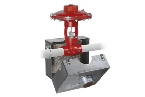
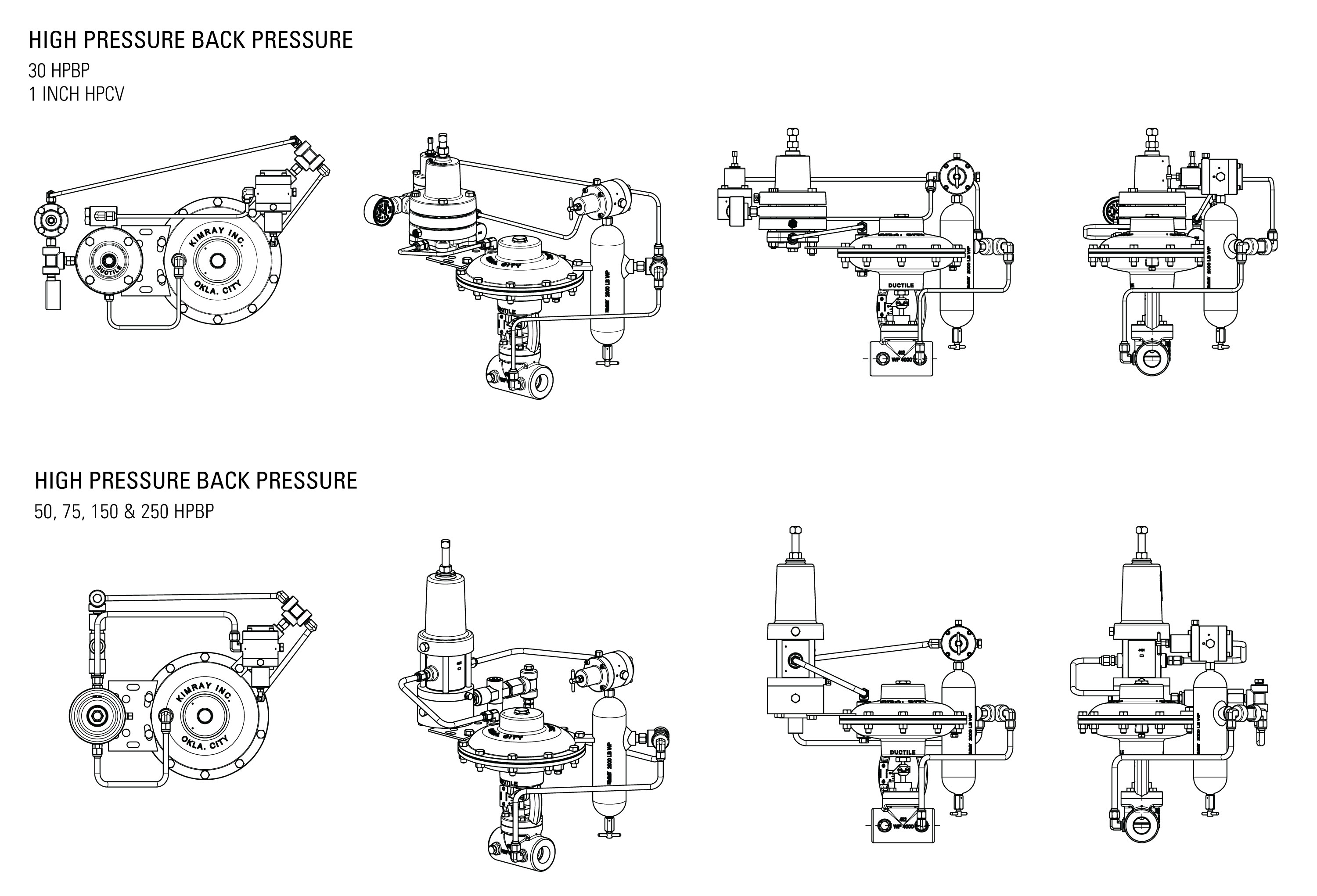
Parts of a High Pressure Back Pressure Package
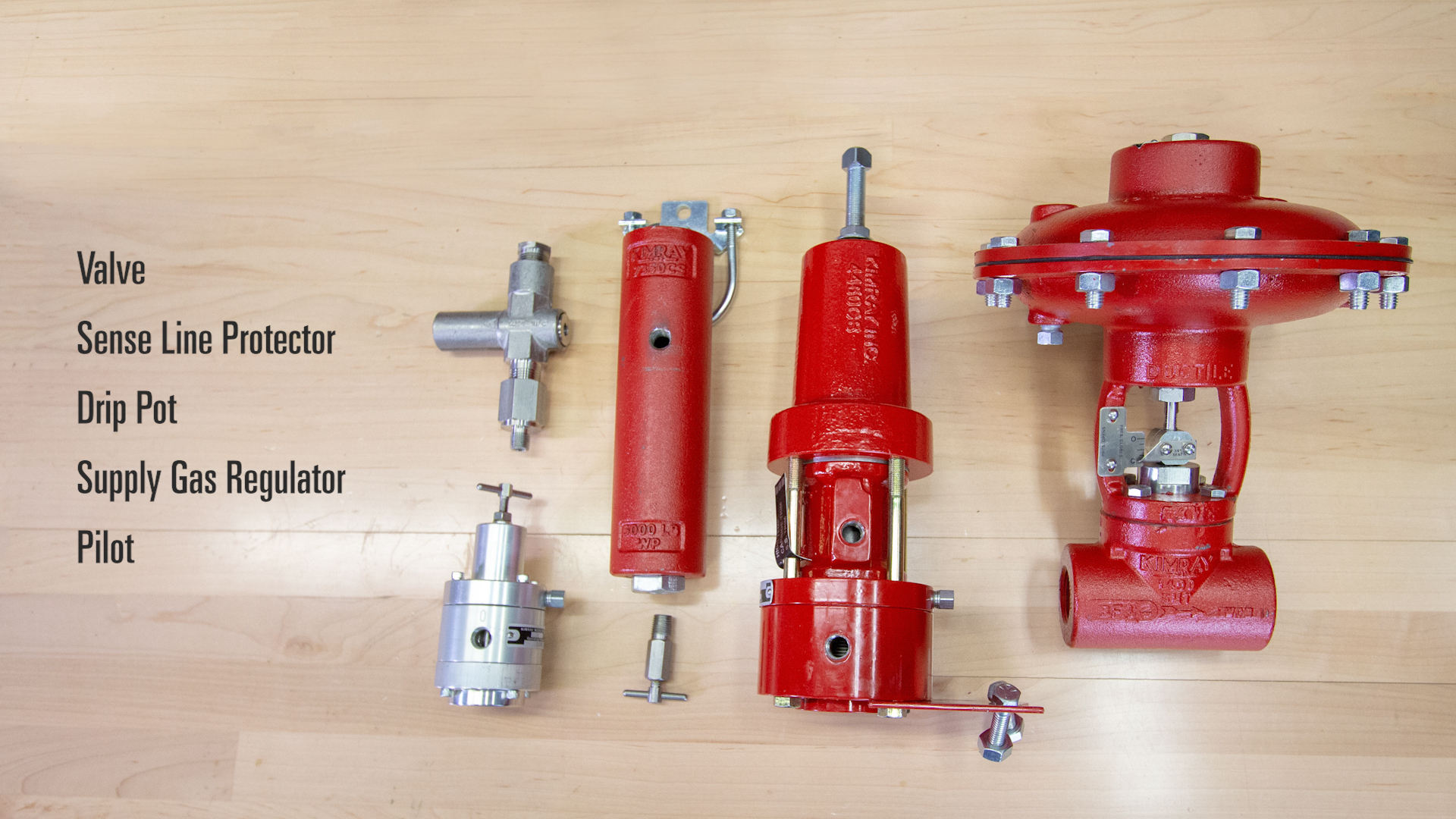
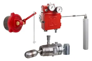
The components of a High Pressure Back Pressure Package include:
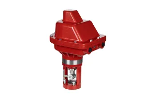
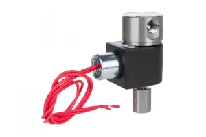
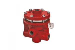
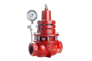
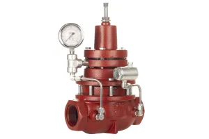
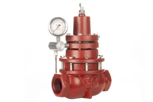
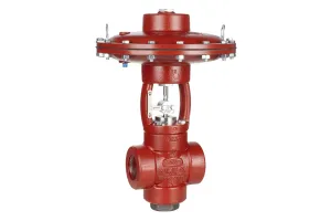
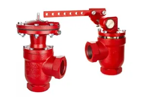
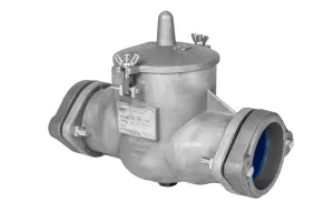
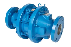
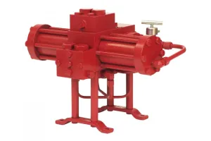
- High Pressure Control Valve
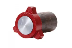
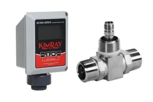
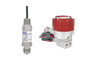
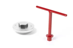
- Sense Line Protector to block out the sensed pressure to a device when it exceeds the adjustable limit
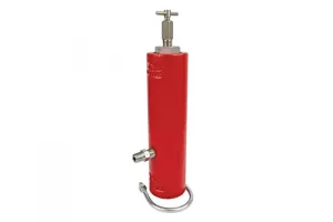
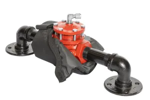
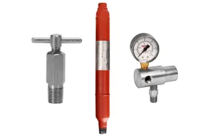
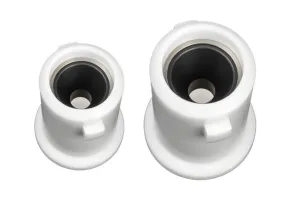
- Drip Pot to knock out any liquid in your supply gas
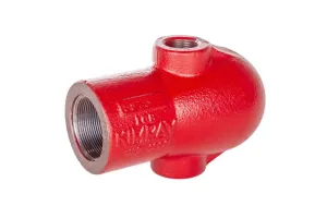
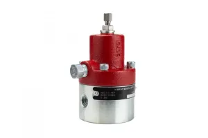
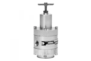
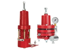
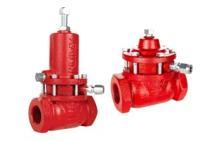
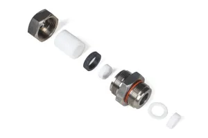
- Supply Gas Regulator to provide supply pressure to the pilot
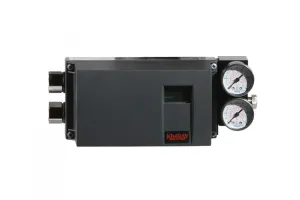
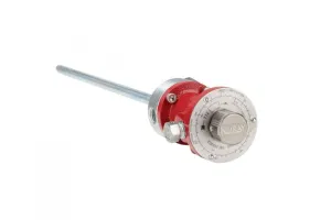
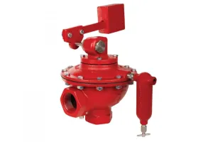
- Pilot to tell the valve what to do
Components Needed
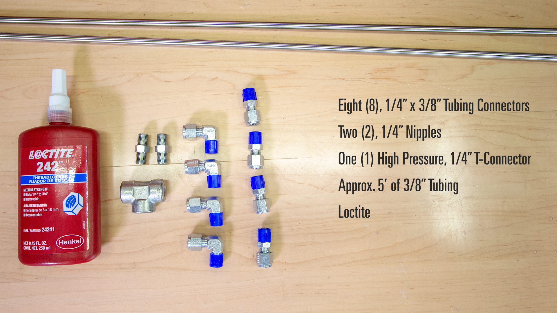
Depending on how you choose to arrange the components, the number of elbow and straight connectors will vary, but we've listed the minimum below:
- (8+) 1/4" x 3/8" Tubing Connectors
- (2) 1/4" Nipples
- (1) High Pressure 1/4" T–Connector
- Approximately 5' of 3/8" Tubing
- Loctite
Tools Needed
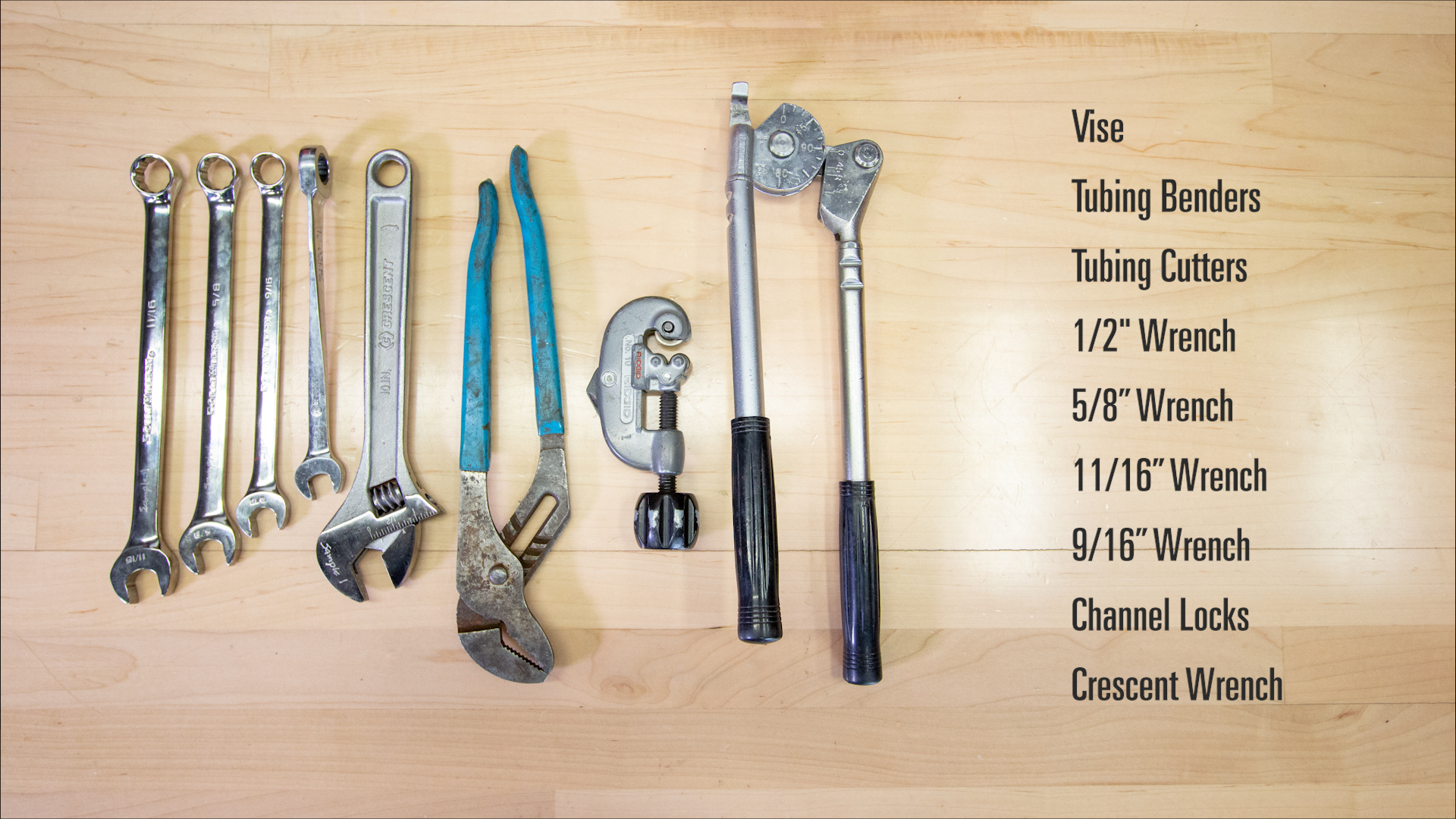
Finally, to put the package together, you’ll need the following tools:
- Vise
- Tubing Benders
- Tubing Cutters
- 1/2" Wrench
- 5/8" Wrench
- 11/16" wrench
- 9/16" Wrench (for bonnet bolts)
- Channel Locks
- Crescent Wrench
If you assemble these packages regularly, you will already have a standard for how to arrange your assembly—whether all of the parts on one side or if it’s more symmetrical.
Knowing this in advance makes it easier to attach the tubing connecters and nipples to the parts before adding them each to the valve.
The way Kyle builds this package in the video will have the components closer together, facing the front of the valve and on the upstream side. We use less tubing this way and avoid creating areas where someone may try to use to lift. From our experience, this arrangement is typically most successful.
How to Build a High Pressure Back Pressure Package
- Thread the needle valve into the bottom of the drip pot.
- Connect the SGR to the drip pot with a ¼” nipple and Loctite.
- Mount the valve body in a vise.
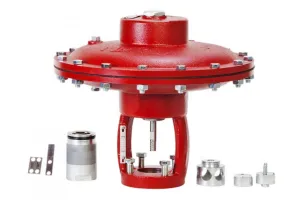
Back pressure valves need to be fail open (pressure close). All of our Kimray valves come standard as fail close, so if you’re building a back pressure package yourself, you’ll need to flip the top works before you begin.
- Remove a bolt from the bonnet on the upstream side and attach the drip pot and SGR on the valve.
- Now we’ll install the pilot to the front of the valve by removing two bonnet bolts, and attaching the bracket included on the pilot.
- Next, install a nipple into the outlet of the sense line protector with Loctite. Connect that into the sensing port of the pilot. Attach the ¼” T into the sense line protector inlet.
- Install one tubing connector into the T, and another into the upstream side of the valve body.
- Bend, cut and install the tubing from the upstream of the valve to the T.
- Install a tubing connector on the T, and another on the drip pot inlet. Connect these together with tubing.
- Attach tubing connectors to the outlet of the supply gas regulator and the supply side of the pilot and install the tubing.
- The supply gas regulator cuts down the supply gas to the required 30PSI of the pilot. This is preset, so you won’t have to adjust it.
- Attach tubing connectors to both the output of the pilot and the top of the valve bonnet. Cut, bend and install the tubing.
- Finish by installing a pressure gauge on the supply gas regulator. (Another gauge can be installed on one of the two sensing ports on the pilot. This is to see your sense pressure.)
- The output of the pilot sends a pneumatic signal to the valve diaphragm, closing the valve.
Note: For this package, you may be using a 30 HPG pilot instead of a high pressure pilot. For this configuration, the assembly will be the same, but the tubing lengths and angles will look different.