With the increasing use of automation in the oil and gas industry, electric controllers have become more common.
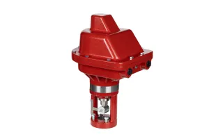
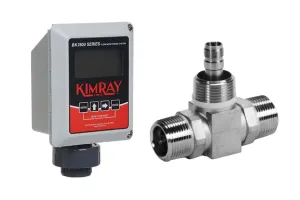
In this video, we’ll be talking about the Kimray Electric Level Switch. I'll show you how it works, how to select the right model, how to install it, and how to wire it to the Kimray Electric Actuator.
How The Electric Level Switch Works
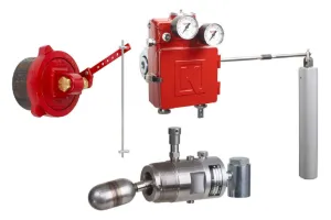
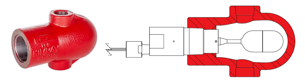
A liquid level switch can be used as a high-level or low-level switch in a pressurized vessel and works similarly to a light switch. When the electrical circuit is completed, the switch sends out a signal. When the circuit is interrupted, the signal is removed.
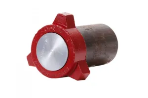
The float is hollow, so as liquid level increases it rises up.
On the other end of the float is the float lever, which contains a magnet. When the magnet in the float lever is close enough to the reed switch, it will complete the circuit and send an electric signal to the control valve.
When liquid level decreases, the magnet will move away from the reed switch interrupting the circuit and removing the signal.
Level Switch Options & How to Select
There are several different options for the Kimray Electric Level Switch, so we’ll look at each parameter separately.
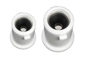
Connection Sizes
- There are two connection sizes available, based on your site needs: 1-½” and 2”.
- All end connection options are male NPT.
Materials
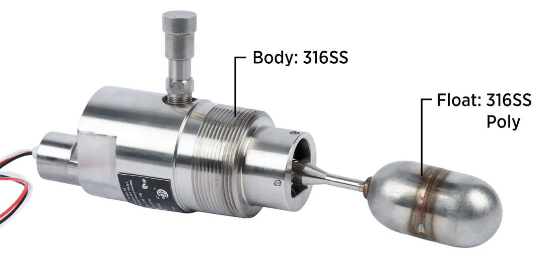
There are two materials options for the float.
- The standard 316SS is great for most conditions.
- High-density polyethylene (HDPE, a.k.a. Poly) is ideal for low density fluids such as condensates, or where hydrocarbons are floating in something that is light or aerated.
- All electric level switch bodies are made from 316 stainless steel and are NACE compliant.
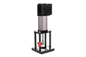
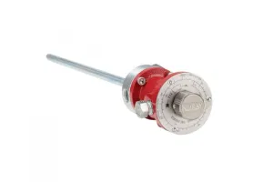
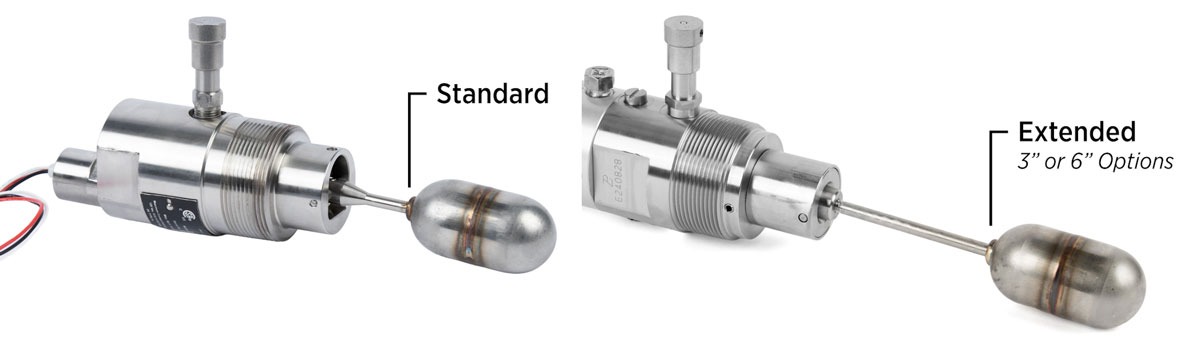
Extension
The standard float arm is great for most uses; however, if you need more clearance in your vessel, there is an optional 3” or 6” extension arm. Note that the extended models require a syntactic float (not shown in image).
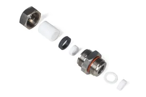
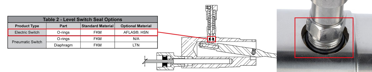
Seal
The standard O-ring seal on the manual override is made of FKM, but AFLAS and HSN are optional for corrosive and/or high temperature conditions.
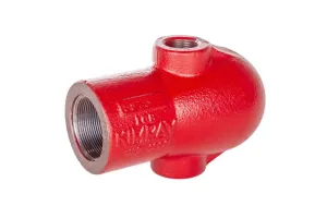
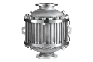
Orientation
The standard float orientation is horizontal; however, we offer one vertical orientation which can be used to insert into the top of a vessel instead of through the side.

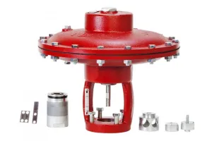
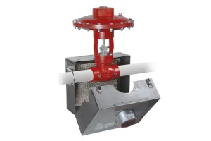
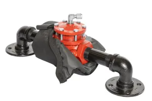
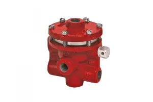
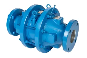
Float Cage
Another option for the float is to use an external float cage to separate the float from the turbulence that occurs inside the vessel. Depending on your location, this could be a required setup to control the level from outside the vessel or entirely based on build preference.
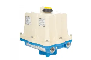
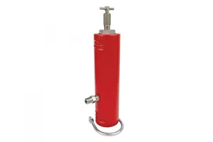
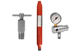
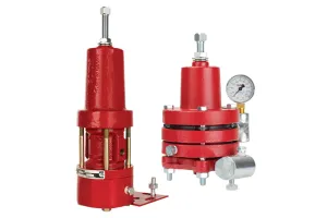
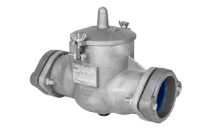
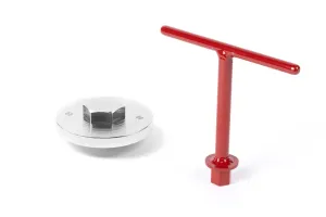
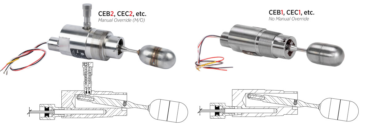
Manual Override
The manual override button is a convenient way to test the function of the level switch by manually actuating the float. This allows you to verify that the dump valve and level switch are operating correctly.
While this can be very helpful to have, some prefer fewer wearable parts and favor the non-manual override option instead.
Maximum Available Working Pressures
There are two MAWP ratings available: 2000 PSI or 5000 PSI. The 5000 PSI models have no manual override, require a Poly float and are only for horizontal displacers orientation.
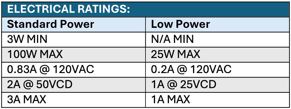
Standard vs Low Power
The Kimray Electric Level Switch is designed to operate in very low power ranges, typically provided by PLCs, TRUs and other distributed control systems.
- The standard power models only require 3W minimum.
- However, if you’re running lower power on site, the low power models have no minimum watt requirement.
Installation
Installation of the Kimray Electric Level Switch is simple, but there are a few things to note.
- First, make certain the float and extension rod are tight before installing.
- Next, use Nickel-impregnated PTFE thread tape or an equivalent on the threads.
- Verify that the level switch pressure connection is tight before pressurizing the system.
- If a manual override is present, it could be oriented on either the top or bottom depending on the application.
- Electric switches do not have a direct or indirect mode since the action is dependent on the wiring. Instead, you only need to consider standard or inverted orientation.
- If you are installing it for low level shutdown, you will want to install it inverted, with the button on the bottom. This will keep the test button functional and allow the switch to signal a valve only when the level gets low enough for the float to drop.

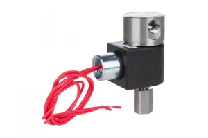
Wiring
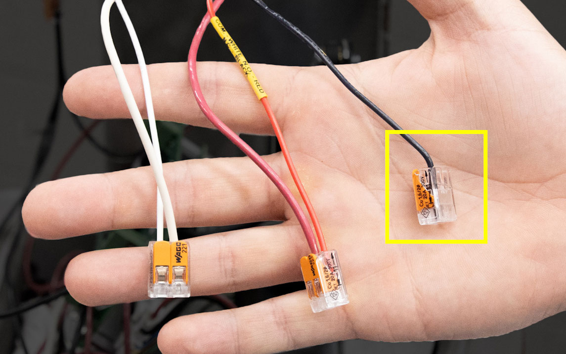
 For wiring, you’ll notice there are three wires connected to the switch. You will always use the white wire and depending on your setup, you will either use red or black. The other will be capped off.
Red is “Normally Open”
If this wire is used for installation, that means without power applied (in other words, without the circuit being completed internally), that’s the position it stays in. This is typically used for high level shutdown. It will not send a signal to the controller until the float is raised and the circuit complete.
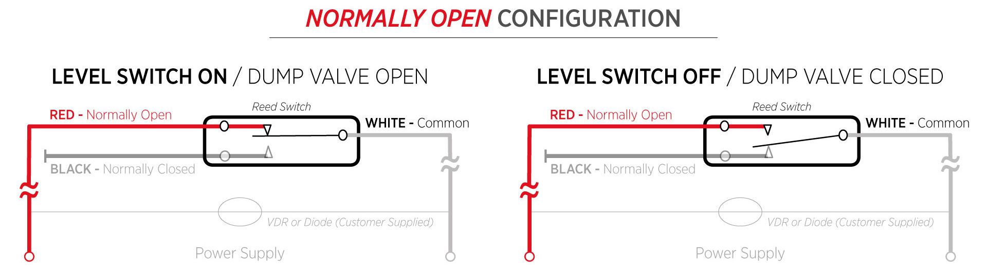
Black is “Normally Closed”
If this wire is used for installation, that means the actuator will move when the circuit is open; it always has a steady signal; it’s waiting for the removal of the signal. When the actuator has no signal, it closes. This is typically used for low level shutdown.
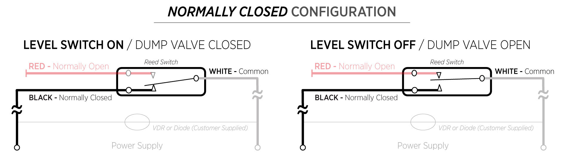
White is “Common”
The white "common" wire will always be run to the actuator. It will be used for the voltage in.
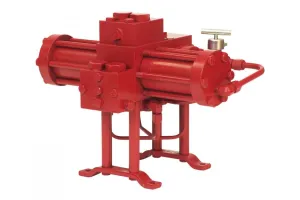
Wiring Process
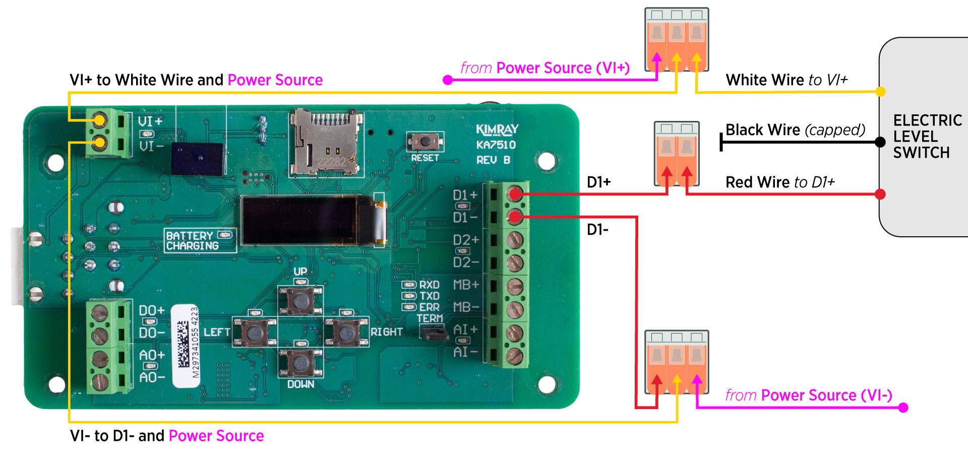
Now let’s wire a CEC2 and a Kimray Electric Actuator for a high level shutdown application (normally open). Be sure you’re wiring according to the diagrams found in the Electric Actuator IOM.
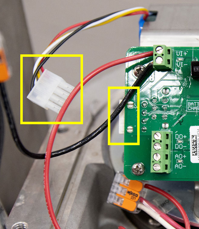
- Make sure the main power is off and that the battery has been disconnected so there is no power running to the actuator.
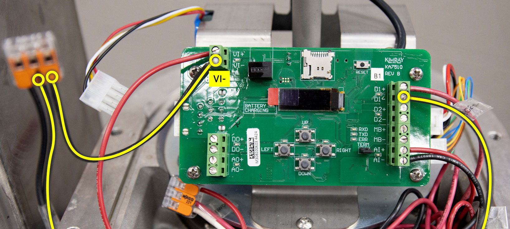
- Since we want the switch to be normally open and only send a signal to the actuator when the production fluid rises too high, we’ll be using the red wire. Connect the red wire to the D1+ on the Electric Actuator.
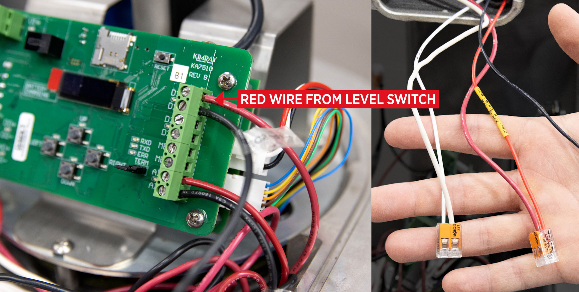
- Cap off the normally closed black wire.
- Next, take the white “common” wire and connect it to VI+. We'll be using connectors to share main power from the actuator.
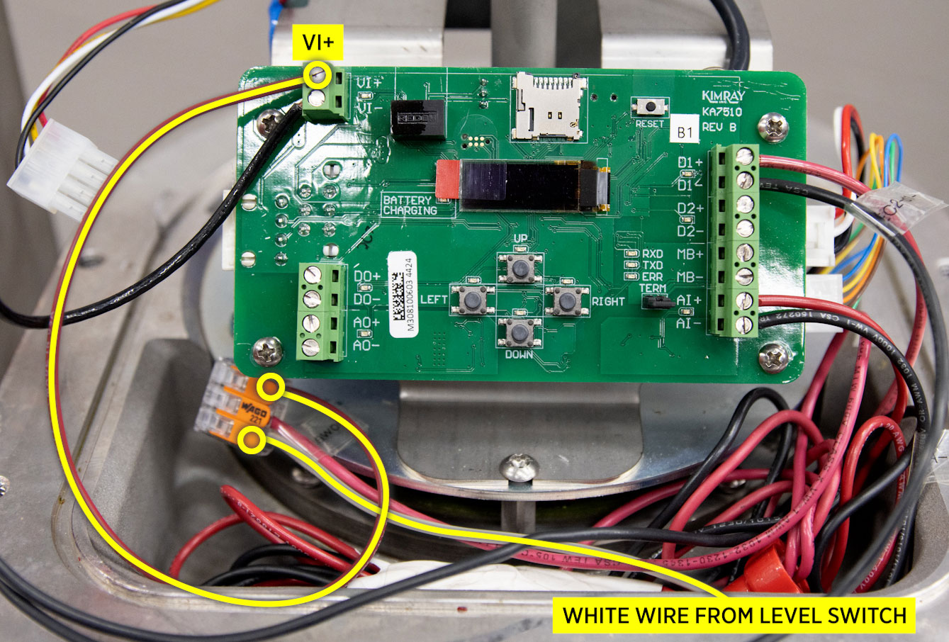
- Connect VI- to D1-. Again, we'll be using connectors to share main power from the actuator.
- Once the battery has been reconnected and power restored to the controllers, the programming can be completed. For steps regarding this information, watch our video about programming the Kimray Electric Actuator used for dump applications.
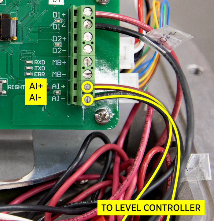
Note: the A1+/- are connected to a level controller and are unrelated to the level switch.
For any questions about this process or anything else regarding the Kimray Electric Level Switch, reach out to me or anyone else on our Technical Sales Support.