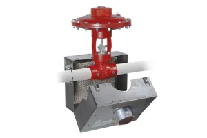


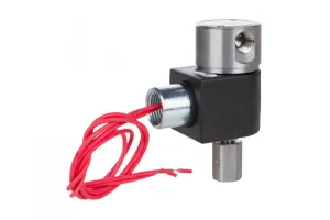
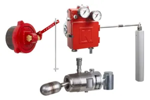


In this training, we will assemble, wire, calibrate and program the Kimray Electric Actuator for dump applications with an LPHV valve. Specifically, we will be showing the set up for liquid gap control using two electric level switches, though the principles and steps shown here will help get you started for setting up any dump application.
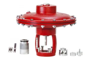
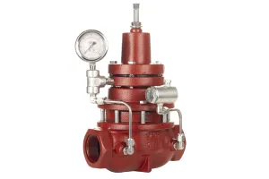
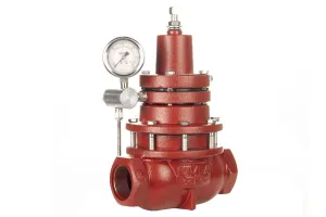
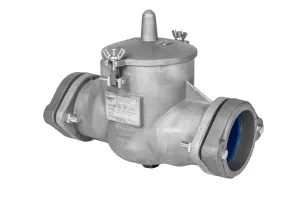
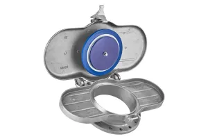
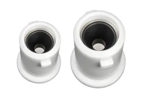
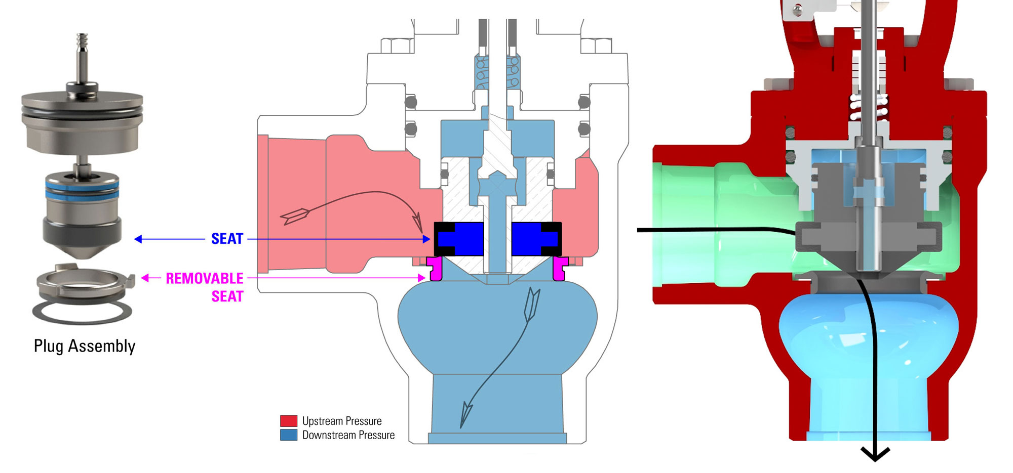 The Low Pressure High Volume Valve (LPHV) is designed with durable trim specifically for erosive conditions– lasting more than 10x longer compared to other valves’ trim in extremely erosive conditions. It is also the first Kimray low pressure dump valve that can be electrically actuated.
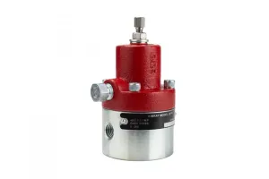
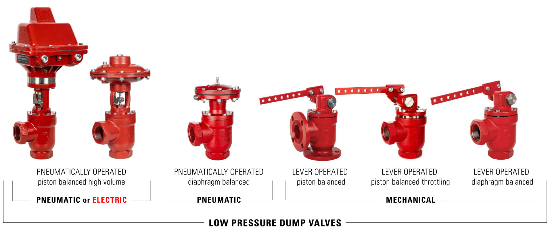
Beyond the Basics with Pneumatically Operated Liquid Dump Valves
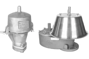
In this video, we’ll be setting up a 2” LPHV, which uses a 1” Electric Actuator. Be aware that for the LPHV, your actuator size will be different than the end connection size of your valve.
| LPHV BWKS End Connection | Electric Actuator |
|---|---|
| 2" | ZAA (1") |
| 3" | ZAB (2") |
| 4" | ZAC (3-4") |
| 2" LPHV Tools | 3" & 4" LPHV Tools |
|---|---|
| 1/2" Socket | 5/8" Socket |
| 1/4" Socket | 7/16" Socket |
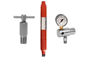
| Wiring Tools |
|---|
| Termination Screwdriver |
| Wire Stripper |
Assembly
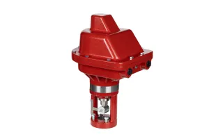
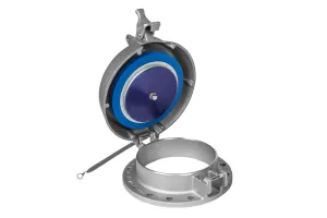
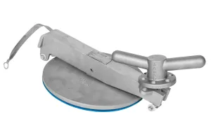
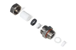
Attach Electric Actuator to LPHV bottom works
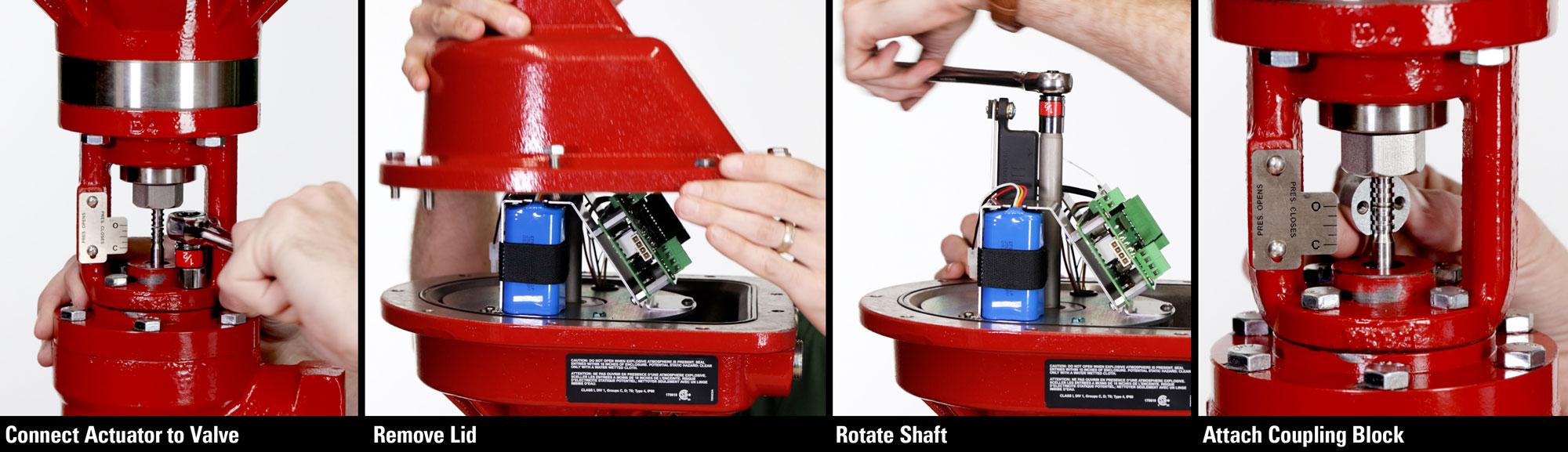
- Place the Electric Actuator on the valve body, oriented so users can easily access the circuit board, and then fully tighten the four bolts.
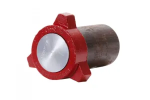
- Remove the lid from the actuator with a 1/2” wrench.
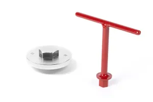
- Using a 1/2" socket or wrench, manually turn the shaft to adjust the stem down until it touches the trim stem.
- Attach the coupling block to the stems with a socket wrench.
Wiring
Note that for a 24V application, 21V is the minimum voltage required. Be sure that your wire gauge and length are acceptable to receive sufficient voltage.
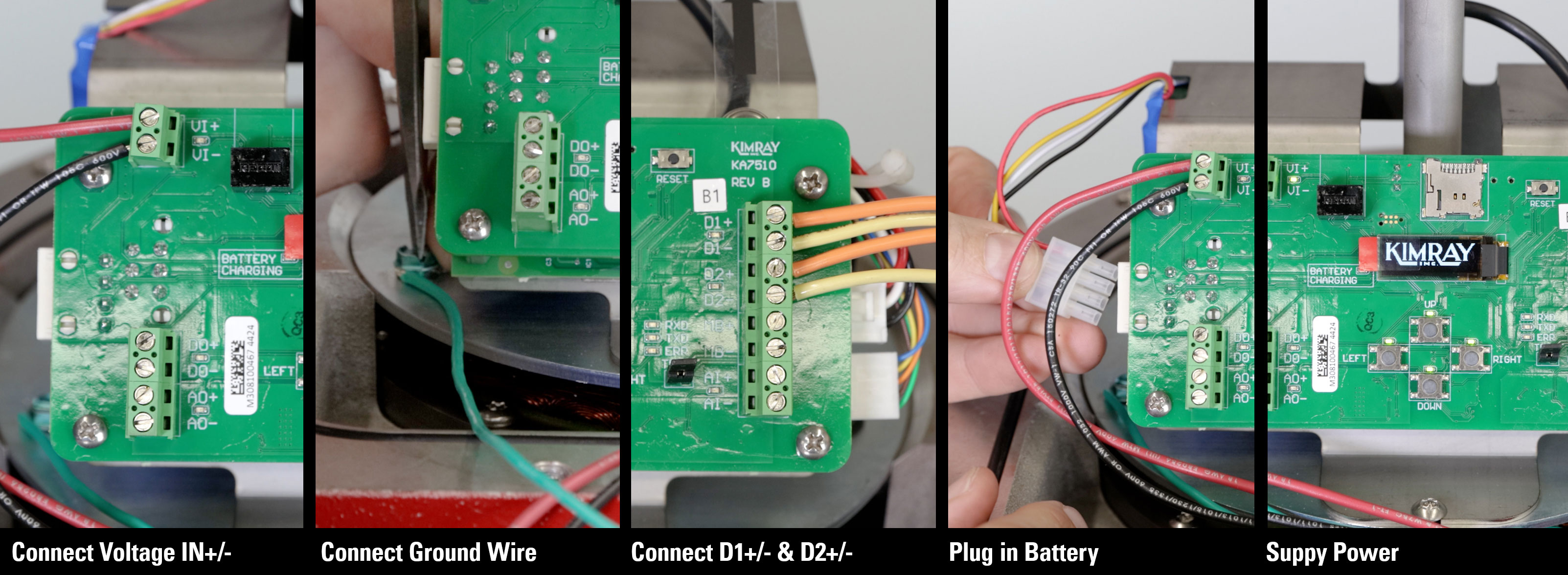
- Attach the ground wire to the grounding screw inside the electric actuator.
- Running your wires through the electrical conduit, connect the power wires to the actuator in the Voltage IN Positive and Voltage IN Negative terminals.
- In our scenario, DISCRETE 1 will be the high level switch, and DISCRETE 2 will be the low level switch. We won’t be showing the whole process of connecting your electric level switches but be sure to follow all proper wiring instructions from your IOM. For our example, we are simulating the two signals from our demo unit.
- You can now plug in the battery backup
- The final step is to supply power to the valve package.
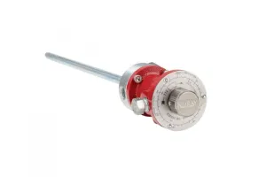
Electric Actuator Calibration

With power supplied to the Electric Actuator, we can begin calibration.
- Upon startup the screen will display CALIBRATE PRESS RIGHT.
- Press RIGHT and the screen will show FINDING OPEN.
- Once fully open, it will display FINDING HOME and drive closed. This will take approximately 35 seconds to complete before returning to the main operating screen.
Indicator Scale
- After calibration is complete, adjust the indicator scale so the indicator is aligned with the closed mark.
- Hammer the scale into place.
Electric Actuator Programing
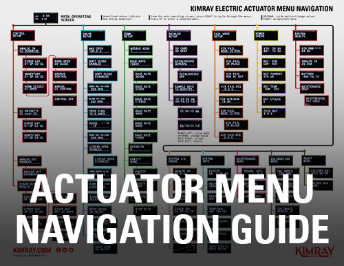
Now we can select our set points on the Electric Actuator.
- Press RIGHT to get to CONTROL SETUP.
- Press DOWN to enter the menu.
- Press UP/DOWN to toggle your desired discrete control setting. We will be using DISCRETE LATCH.
- A latch signal means that the high liquid level switch maintains the switch position until changed by the low liquid level switch. A momentary signal only exists while the input from the liquid level switch is active, returning to its original position when the input is released.
- Press RIGHT to choose DISCR LAT D1-OP D2-CL.
- Next, press UP or DOWN to select discrete priority of D1 over D2.
- Press RIGHT.
- Now you have the option to enable or disable the ANALOG OUT. We will choose to disable and press RIGHT.
- You can also change your control speed, acceleration and many other optional controls by following the menu prompts in the IOM.
- Press left until you get back to the main operating screen
Setting the time and date
It’s best practice to also set the date and time on the Electric Actuator. With any datalogging, you’ll want to have an accurate record of when events happened.
- From the main operating screen, press RIGHT until you get to DATALOG SETUP.
- Press UP to enter the menu.
- Press RIGHT until you see the time and date.
- Then press UP.
- From here, press RIGHT or LEFT to select a field and UP or DOWN to change the value.
- HOLD RIGHT to accept the set time.
- Now do the same for the date, then HOLD RIGHT to accept.
Now your Electric Actuator package is set up. If you have questions about the Kimray Electric Actuator for your specific site, contact Kimray Customer & Product Support.