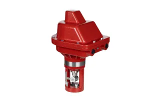
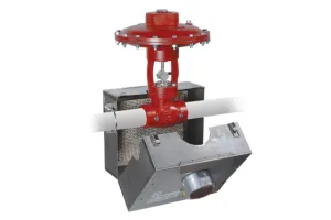
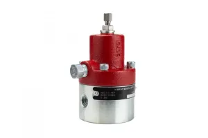
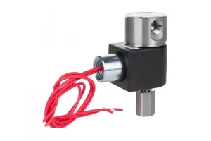
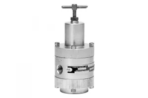
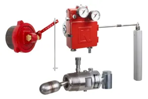
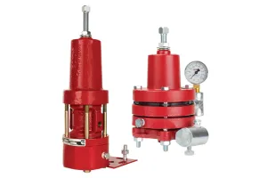
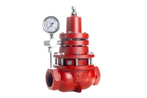
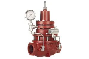
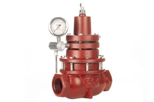
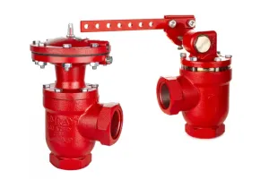
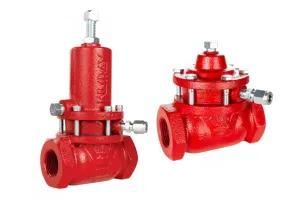
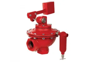
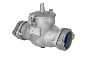
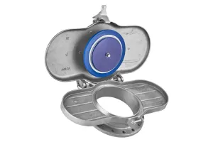
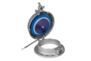
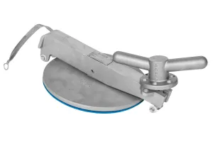
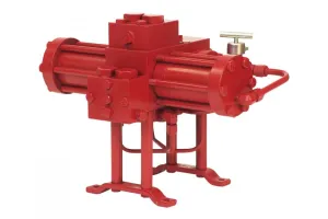
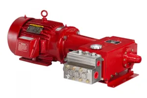
A bellows high pressure pilot is used to monitor and control upstream or downstream pressure between 75 and 2500 PSI.
In a previous video, we showed how to either change the bellows for a different operating pressure or convert from indirect to direct acting. In this video, we’ll be showing how to install a repair kit for regular maintenance.
Before performing any service, make sure the valve is isolated from all gas sources and that the valve package operating and instrument gas lines are completely depressurized. Never loosen any fittings or valve connections while there is pressure in the lines.
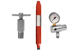
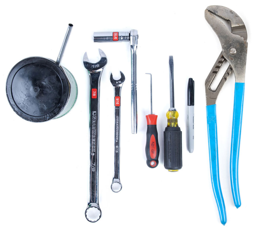 Tools:

- 9/16” Socket or End Wrench (adjusting screw, body bolts, pilot seat)
- 9/16” Deep Socket Wrench (pilot seat in supply housing)
- 7/8” Wrench (diaphragm nuts)
- Channel Locks (if diaphragm plate is stuck)
- Flathead Screwdriver
- Pick
- Grease
- Marker (optional)
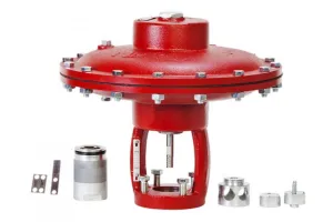
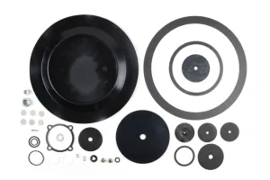
- Repair Kit (RBQ)
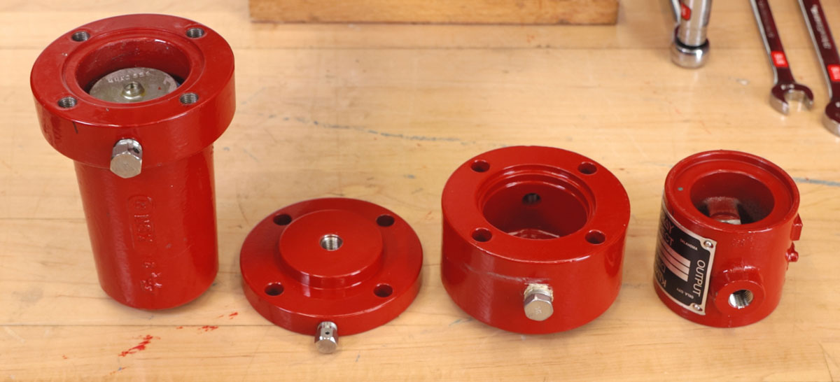
Disassembly
- To begin, make a mark on the pilot so that aligning the components will be easier later during assembly.
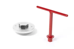
- Next, remove the adjusting screw with a 9/16” wrench.
- Remove and discard the washer and packing seal.
LOWER HOUSING
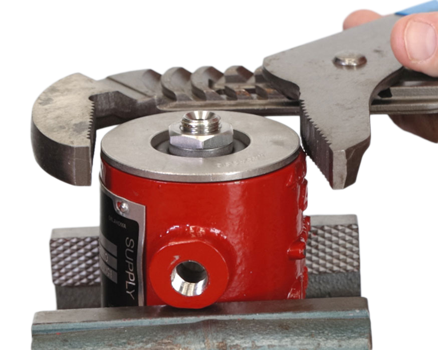
- Turn the pilot upside down and secure it in a vise.
- Use a 9/16” wrench to remove the four screws from the body.
- Separate the lower housing and the main body from the supply body assembly.
- Unthread and remove the bellows. If it doesn’t come off easily, use a rag for a better grip.
- Remove and discard the O-ring on the bellows.
- Then remove and discard the O-ring on the main body.
- Separate the supply body from the bonnet
- If the diaphragm plate is stuck to the bonnet, you can remove it now.
- Use channel locks to remove the diaphragm plates if they are stuck to the supply body.
- Pull out the seat housing assembly & stem assembly. You may need to use a screwdriver placed under the diaphragm.
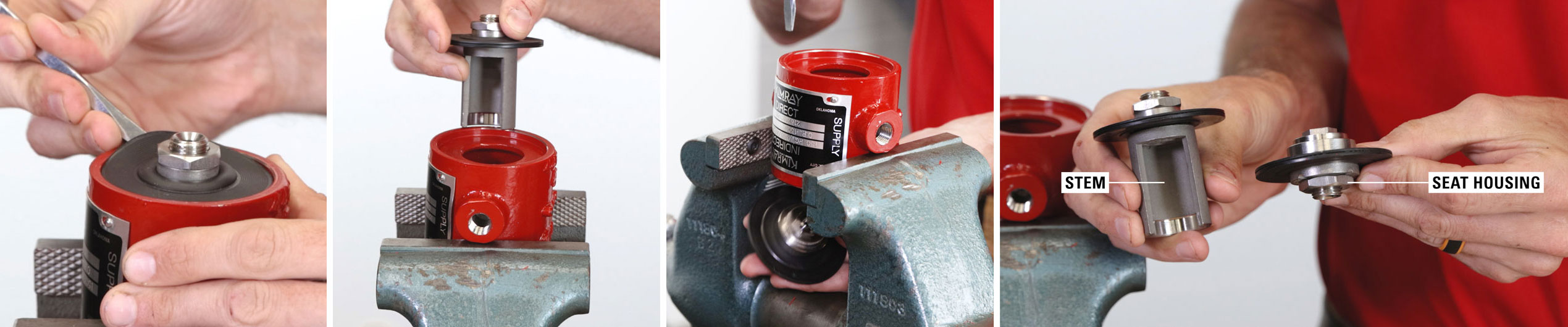

STEM
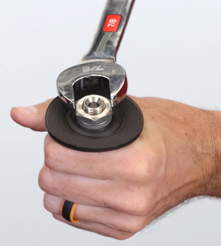 While holding the stem assembly, use a 7/8” wrench to remove the diaphragm nut followed by the spacer. Keep both pieces for assembly.
- Remove and discard the diaphragm.

SEAT HOUSING
- Next, while holding the seat housing assembly, use a 7/8” wrench to remove the diaphragm nut followed by the spacer. Keep both of these pieces as well.
- Remove and discard the diaphragm.
- Use a 9/16” wrench to separate the pilot seat from the seat housing assembly. Discard the pilot seat with the O-ring.
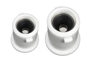
SUPPLY HOUSING
- Finally, turn over the supply housing in the vise and use a 9/16” deep socket to remove and discard the pilot seat, O-Ring, and pilot plug.
- Remove and discard the spring from the housing.
Inspection and cleaning
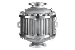
- Inspect the bellows for any sign of damage, cracks or separation in the rings. This can be caused by pulsation or over pressure and will need to be replaced.
- Clean out both breather plugs and thoroughly clean each housing.
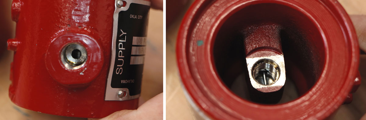
- Take special care to clean out the port from the supply input to the lower seat as it is easy to overlook and can become blocked. Even small debris can clog pilot plug and can cause issues.


Assembly
SUPPLY HOUSING
- Start assembly by placing the bonnet into the vise so it’s ready for later steps.
- We didn’t remove the spring or spring plate during disassembly, but make sure they are still in place at this point.
- Add a small amount of grease to the top of the spring plate.
- Install the #108 spring into the body, small end up.
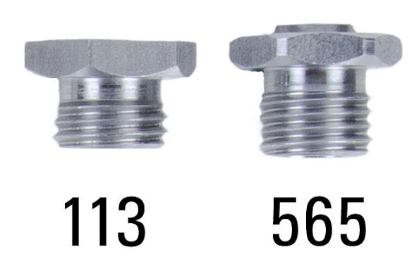
- Install the #265 O-Ring over #565 seat by rolling it over the threads to not damage it.
- Insert the #112 pilot plug through the seat, small ball first.
- Holding it by the pilot plug, install the lower seat into the housing by hand and tighten it with 9/16” socket.

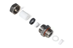
SEAT HOUSING
- Install the #265 O-Ring onto #113 upper seat.
- Then install the upper seat into the seat housing and tighten with a 9/16” wrench.
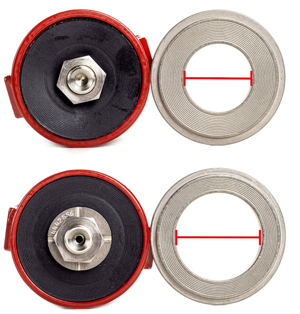
- Install the #4436 diaphragm onto the seat housing. (The #4436 diaphragm has a slightly larger outer diameter than the #4447 diaphragm.)

- Install the #4442 diaphragm spacer on top of the diaphragm.
- Screw on the diaphragm nut with a 7/8” wrench.
- Place the upper seat assembly over the small ball of the pilot plug.
- Then place the #4441SS6 diaphragm plate on top of the diaphragm.
STEM
- Install the #4447 diaphragm over stem.
- Then place on the #4432SS6 spacer ring.
- Screw on the diaphragm nut with a 7/8” wrench.
- Holding the supply housing and diaphragm plate together, flip it over and insert the stem into the supply body. Make sure the diaphragm is properly seated.
- Place the #4443SS6 diaphragm plate on top.
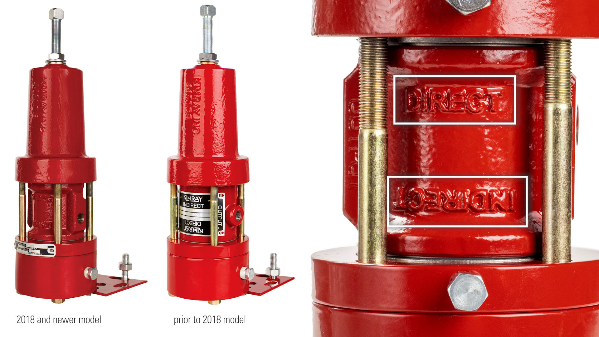
DIRECT / INDIRECT ACTING
- At this time, this is where you will determine the action of the pilot – direct or indirect.
- Set this whole assembly on the bonnet. The words that are upside down will be the action it is, because you’ll be flipping the whole thing over later.
LOWER HOUSING, SUPPLY HOUSING, BONNET
- Roll the #265 O-ring over the threads of the bellows assembly.
- Thread the bellows into the lower housing by hand.
- Install the #802 O-ring over the lower housing.
- Add a small amount of grease to the O-ring.
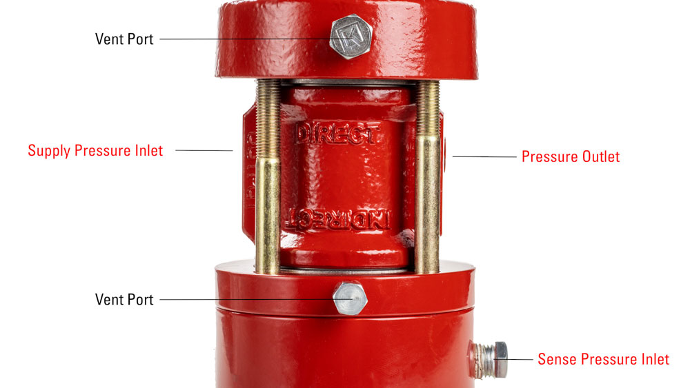
- Install the lower housing on the main body. Push down with your hand, and make sure to align the markings and holes. Operationally, this can be installed in any orientation, but 90° from the sensing ports is best practice for easiest access and installation.
- Using your markings, align the bonnet, supply body and lower housing. The supply port, output port and sensing port will all be aligned.
- Replace the screws and bracket and tighten with a crisscross pattern with a 9/16” wrench, evenly distributing pressure as you tighten.
- Place the new #4491 washer and #4488 packing seal on the adjusting screw.
- Add a small amount of grease to the end of the adjusting screw where it contacts the spring plate and replace it into the body.

POSTED IN: