


A burner management system is a combination of products that oil and gas producers use to provide temperature control on heated vessels.
In this article, we'll cover 5 key components of burner management fuel controls:
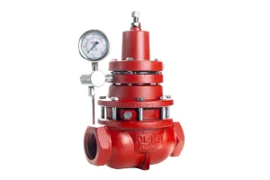
- Air/ Fuel Ratio Control
- Fuel Pressure/ Volume Control
- Burner Design
- Thermostatic Control
- The Stack
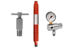
1. Air/ Fuel Ratio Control
The most common problem in the combustion process is maintaining the correct air/fuel ratio in order to extract the maximum BTU from every cubic foot of fuel consumed, and to do so without wasting any fuel.
Fortunately this is easy to correct.
The "stoichiometric ratio" is the ideal air/fuel ratio where all fuel is burned and air is consumed without any excess of either. The stoichiometric air/fuel ratio for methane is 17.2:1.
If the air content in the air/fuel mixture is higher than the stoichiometric ratio, it is considered "lean."
Under this condition, no benefit will be gained from the excess air and the combustion temperature will actually be lower that if the mixture were stoichiometric.
If the air content in the air/fuel mixture is lower than the stoichiometric ratio, it is considered "rich."
Such a condition will also result in a less-than-optimum flame temperature. The unburned fuel will result in unwanted carbon soot formations in the fire tube and stack, as well as contributing to unwanted emissions into the atmosphere.
Rich conditions may also contribute to increased risk of explosion due to unburned fuel remaining in the combustion chamber.
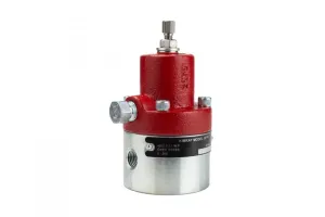
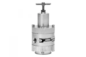
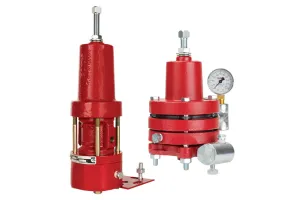
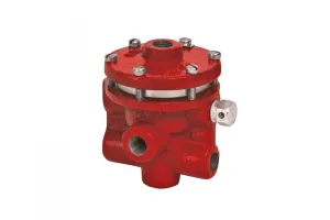
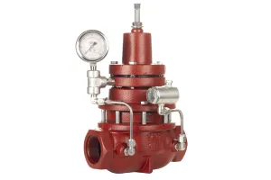
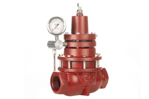
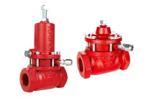
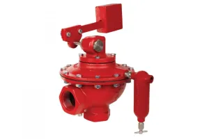
2. Fuel Pressure/ Volume Control
Total amount of fuel burned is directly related to the amount of total heat released, if there is enough air to maintain the proper air/fuel ratio. Typically, a fuel pressure of around 12 PSI will be adequate for a properly sized main burner and pilot.
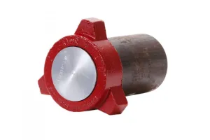
If more total heat is required or the shape of the flame changes, a change in the burner nozzle is needed, assuming there is enough air available to mix with the additional fuel.
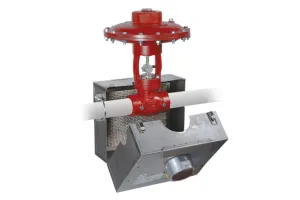
3. Burner Design—Direct and Indirect
A properly designed burner for a direct fired steam boiler will result in a high-volume blast furnace type of blue flame with yellow to red flecks in the flame. The boiler flame will bathe the product tubes in flames.
A proper flame for an indirect heater with a fire tube will be a long, slender blue flame. It should extend to the first bend in the fire tube. The fire tube flame will be a gentle flame, blue with yellow to red tips, and should never touch the fire tube at any place.
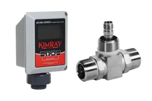
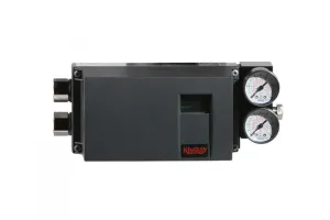
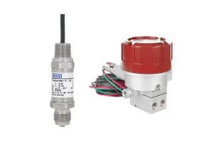
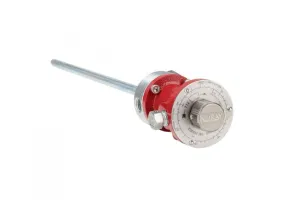
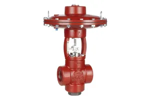
4. Thermostatic Control
Producers can achieve process temperature control with the use of a thermostatic control unit. The thermostatic control may throttle the burner flame or shut it off completely and re-ignite the burner when needed.
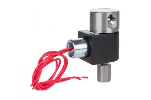
Ignition systems range from a constantly burning pilot to one of several types of pilotless electronic ignitions.
The current trend is toward the electronic ignition systems. These systems eliminate the possibility of a constant pilot being blown out and minimize fuel consumption and atmospheric emissions.
Electronic ignition systems are also much safer for the operator in the event of a back flash or explosion.
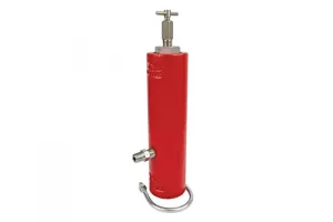
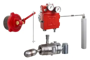
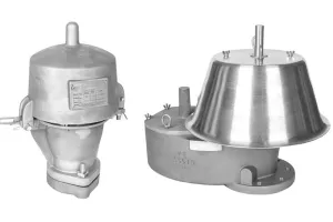
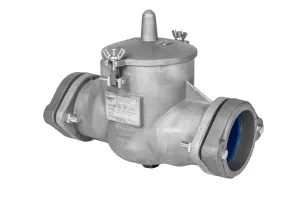
5. The Stack and Burner Management
A properly designed stack is one of the most critical elements to achieve the correct air/fuel ratio with a burner.
It is the hot exhaust gasses from the burner rising up through the stack that create a low pressure area at the air inlet to the combustion chamber.
An improperly designed stack will not create enough upward draft to draw enough air into the combustion chamber. This will result in an improper proper air/fuel ratio. The resulting rich burning flame will be cool, yellow, and will cause excessive smoke out the stack, carbon soot build up in the fire tube, and overall poor performance.
OEMs design the the inlet air controller, fire tube, burner, and stack as a unit. Most units will have some sort of adjustable air controller. This allows the operator or technician to adjust the amount of air available and minimize excess air to the burner.
OEMs may also design an anti-downdraft stack head on the upper end of the stack. This minimizes the chance of a pilot going out when the main burner cycles off.
The fire tube, with no fire inside, becomes an air-cooled heat sink that quickly cools any process fluid surrounding it.
To speak with an expert about optimizing your burner management system, contact your local Kimray store or authorized distributor.