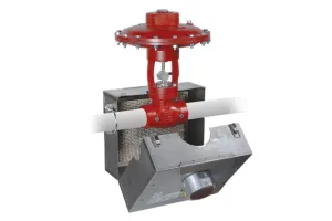

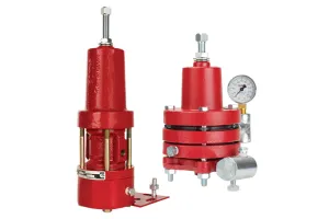
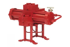
Electric Actuator & Electric Pilot Assembly
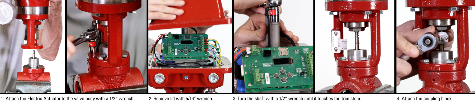
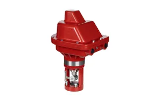
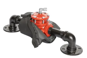
Attach Electric Actuator to Valve Body
 Place the Electric Actuator on the valve body, oriented so users can easily access the circuit board and fully tighten the four bolts.
- Remove the lid from the actuator with a 1/2” wrench.
- Using a 1/2" wrench, manually turn the shaft to adjust the stem down until it touches the trim stem.
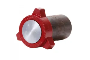
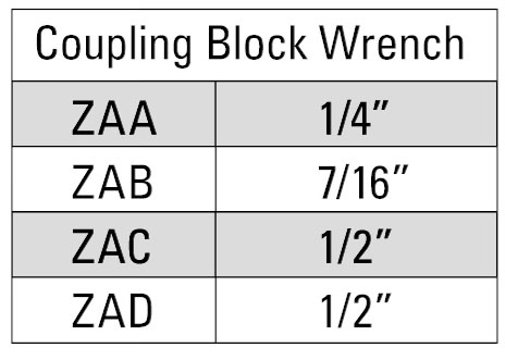
- Attach the coupling block to the stems with a socket wrench.
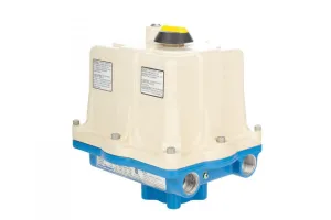
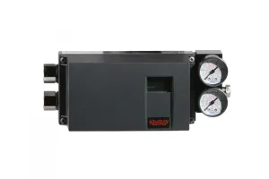
Attach Electric Pilot to Electric Actuator
There are many ways to attach the Electric Pilot, and users will need to understand their own needs and set it up accordingly. Your pilot may be located farther away, or you could choose to use one of the other ports on the actuator. Perhaps several actuators are being daisy chained together, or one of many other reasons. Based on this setup, you can make assumptions for your own site.
- For all connections, be sure to use piping best practices.
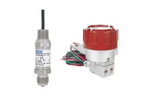
- For our package, we are using a ½" nipple connection from the Electric Actuator to a Class 1, Div 1 explosion proof junction box. Alternatively, there is space in the Electric Actuator to store the wires and connectors.
- From the junction box, we have another ½" nipple connection to the electric pilot.
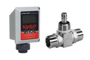
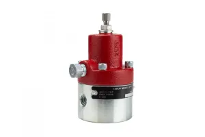
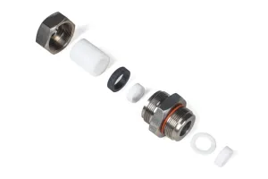
Attach 4-20mA Transmitter to Electric Pilot
 The term transducer and transmitter are often used interchangeably. A transducer sends a signal in volts and a transmitter sends a signal in milliamps.
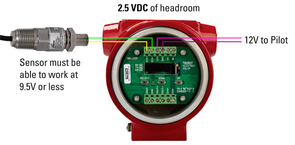
The YEP requires a 4-20mA input. Approximately 2.5 VDC of headroom is required for protection and detection of the analog sensor. For example, if 12V is supplied to pilot, the sensor must be able to work at 9.5V or less.
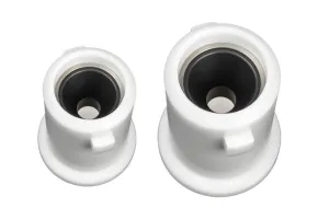
For most pressure regulation applications, attaching the transducer to the bottom of the Electric Pilot is ideal; however, your transducer could be farther downline.
For the purposes of this video, we are using a demo unit with a simulated 4-20mA signal. For most installations, the signal will come from a pressure transmitter.
Wiring
To connect the wires, you’ll need a 7/64” hex wrench to remove the Electric Pilot circuit board, wire strippers, and a termination screwdriver.
- First, use a 7/64” hex wrench to remove the circuit board from the Electric Pilot so that you can access the termination ports.
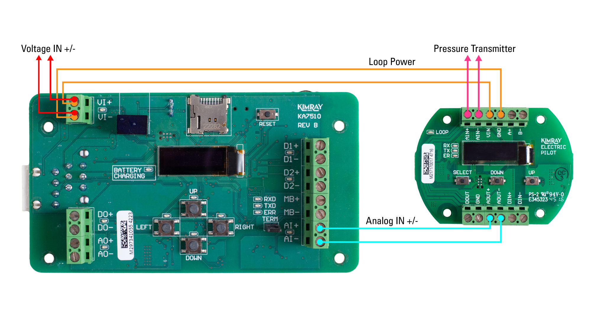
- Take the wires coming from your analog pressure transducer and terminate them to the Electric Pilot in the Analog IN positive and Analog IN negative terminals.
- Next, connect a set of wires in the Analog OUT positive and Analog OUT negative terminals of the pilot. Terminate these wires to the Analog IN positive and Analog IN negative terminals on the Electric Actuator.
- Attach the ground wire to the ground screw on the actuator.
- Connect the power wires to the Electric Actuator in the Voltage IN Positive and Voltage IN Negative terminals. Note that for a 24V application, 21V is the minimum voltage required. Be sure that your wire gauge and length are acceptable to receive sufficient voltage.
- The Electric Pilot can run off loop power. To do this, connect wires from the Voltage IN +/- terminals on the Electric Actuator to the Voltage IN and Ground terminals on the Electric Pilot.
- Discrete Override Wiring: D1+/- and D2+/- are for discrete override. For pressure regulation, there are not many occurrences where you will be using these terminals. We will go over the wiring and programming for a dump application with discrete override in a separate video.
- Attach the ground wire to the ground terminal on the Electric Pilot.
- Secure the Electric Pilot circuit board back into place, keeping the wires as tidy as possible behind the board.
- You can now plug in the battery backup on the Electric Actuator.
- The final step is now to supply power to the valve package.
Electric Actuator Calibration

With power supplied to the Electric Actuator, we can begin calibration.
- Upon startup the screen will display CALIBRATE PRESS RIGHT.
- Press RIGHT and the screen will show FINDING OPEN.
- Once fully open, it will display FINDING HOME and drive closed. Depending on your valve size, this should take about 35 seconds to complete. A calibration graph will show momentarily before returning to the main operating screen.
Electric Actuator Programming
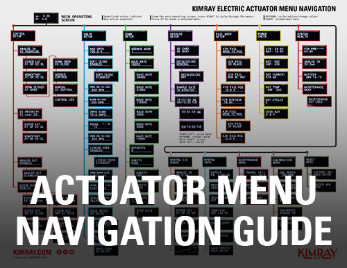 Now we can select our set points on the Electric Actuator for back pressure regulation. First, we will adjust the CONTROL SETUP menu to tell the actuator what to do with each input.
- From the main operating screen, press RIGHT to get to the CONTROL SETUP menu.
- Press DOWN to enter the menu.
- Press RIGHT again to select ANALOG IN D1 OVERRIDE. This means we’re controlling Analog IN and there’s also a discrete override which is optional. Choose the best option for your application by pressing RIGHT to select it.
- This will take you to the next set of options to select your preferred discrete priority. We will select D1 over D2 and press RIGHT.
- This next menu is to enable or disable the ANALOG OUT. We are not using analog out in this example so we will set it to DISABLE and press RIGHT.
- The last menu is to enable or disable DISCRETE OUT. Press UP or DOWN to select then press RIGHT to accept.
- Press LEFT to return to the main menu.
At this point, the Electric Actuator is ready to go with all other options set to their default setting. You can change your control speed, acceleration and many other kinds of optional controls by following the menu prompts in the IOM.
Datalogging
MicroSD Card & Sample Rates
As a default setting, datalogging is activated, but you can change your sample rate in the options. For datalogging, you will need a microSD card. 16-32GB is more than sufficient since a 1MB file can contain more than two months of data at the default sample rate.
- Insert a microSD card into the slot above the screen on the circuit board. From the main operating screen, press RIGHT until you see DATALOG SETUP.
- Press UP to enter the menu and you will see SD CARD OKAY.
- To change the sample rate time, press RIGHT until you see SAMPLE RATE, then press UP or DOWN to adjust the value. (1-60 seconds, 1-59 min, or 1-12 hours)
Setting the time and date
It’s best practice to also set the date and time on the Electric Actuator. With any datalogging, you’ll want to have an accurate record of when events happened.
- From the main operating screen, press RIGHT until you get to DATALOG SETUP.
- Press UP to enter the menu.
- Press RIGHT until you see the time and date.
- Then press UP.
- From here, press RIGHT or LEFT to select a field and UP or DOWN to change the value.
- HOLD RIGHT to accept the set time.
- Now do the same for the date, then HOLD RIGHT to accept.
MODBUS setup
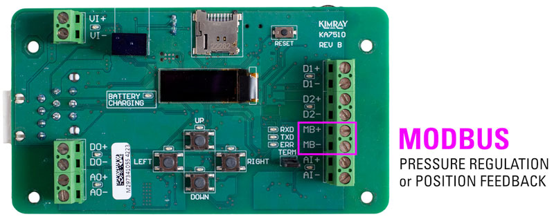
Let’s briefly look at the MODBUS setup.
- First, if you’re using MODBUS for pressure regulation or position feedback, you would use terminals MB+/- instead of AI+/-.
- After calibration, you will still need to enter the CONTROL SETUP menu. Press RIGHT to CONTROL SETUP, then press DOWN to enter the menu
- Press DOWN until you see MODBUS CONTROL and then press RIGHT to enter the menu.
- From here you will now select your discrete priority, enable or disable your ANALOG OUT signal, and enable or disable your DISCRETE OUT signal.
Electric Pilot Programming
Now that the Electric Actuator has been set up, we can finish the installation by setting up the Electric Pilot.
- If the Electric Pilot is new, your screen will display UNDEFINED. If it’s been previously used, you’ll need to reset the pilot by holding the up and down buttons for 5 seconds.
- Once the pilot has been reset, the screen will display the SENSOR TYPE menu.
- Push the UP button once to display PRESSURE, then press SELECT.
- Press UP to select the desired unit, then press SELECT.
- This will automatically take you to the next menu for the maximum working pressure of your transducer. Use the UP and DOWN buttons to set the pressure. Then press SELECT.
- The next menu will set the minimum working pressure of the transducer. Press UP or DOWN to set the amount and then press SELECT.
- The screen will now display the APPLICATION menu.
- Press UP again to cycle through the applications. Press SELECT on Back Pressure
- You will now see the SET VALUE menu.
- Use the UP and DOWN buttons to scroll to your desired set point. Press SELECT to enter that value.
- From this screen you will now see the MODE MENU.
- Press UP to cycle through the options and press SELECT on MANUAL MODE.
- Move the Controller Output (CO%) to 50% and press SELECT. This will open the valve approximately halfway and allow pressure to flow through.
- Press SELECT until you get back to MODE MENU.
- Press the UP button to AUTOTUNE and then press SELECT.
The Pilot will now send varying signals to the valve to see how it reacts. This should take 10-15 seconds. Once it has completed Autotune, it will automatically move to Run Mode and begin controlling your set value. You can leave the pilot on this screen, and it will move to standby mode after approximately four minutes. If you ever need to change your Set Value, you won’t need to run autotune again. You will only need to do that if you change your valve or trim size.
Securely replace the Electric Actuator lid and the Electric Pilot cover and now you’re set up for back pressure regulation.
If you have questions about the Kimray Electric Actuator, contact Kimray Customer & Product Support.