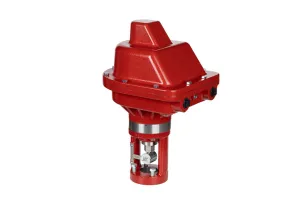
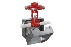
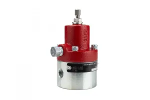
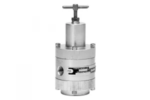
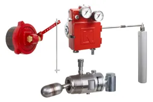
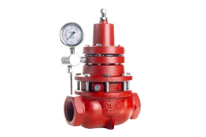
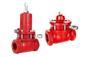
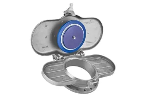
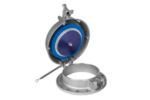
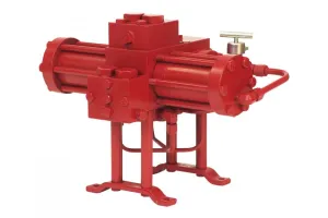
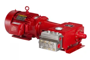
Kimray's Pressure Regulators with Outside Supply are easy-to-operate, environmentally friendly solutions for maintaining pressure set points on oil and gas vessels.
These regulators are designed to accept an outside source of supply to the pilot rather than using the process gas.
When an outside source like compressed nitrogen is used, the regulators provide emissions-free operation.
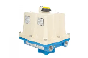
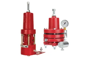
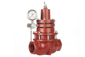
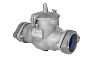
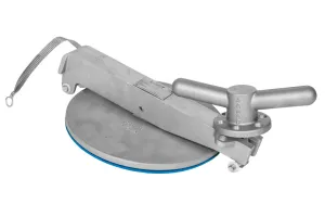
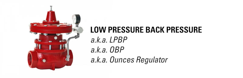
Low Pressure Regulators perform the same function as standard regulators but have lower control ranges. Because of this ability to control small ounces of pressure, you may have heard these informally referred to as “ounces regulators”.
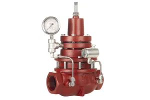
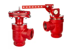
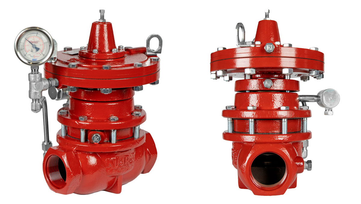
The Low Pressure Back Pressure to Atmosphere was configured for use with outside supply gas. We’ve modified the design and name of this regulator to align with the current line of other Outside Supply Regulators, naming it the Low Pressure Back Pressure Outside Supply.
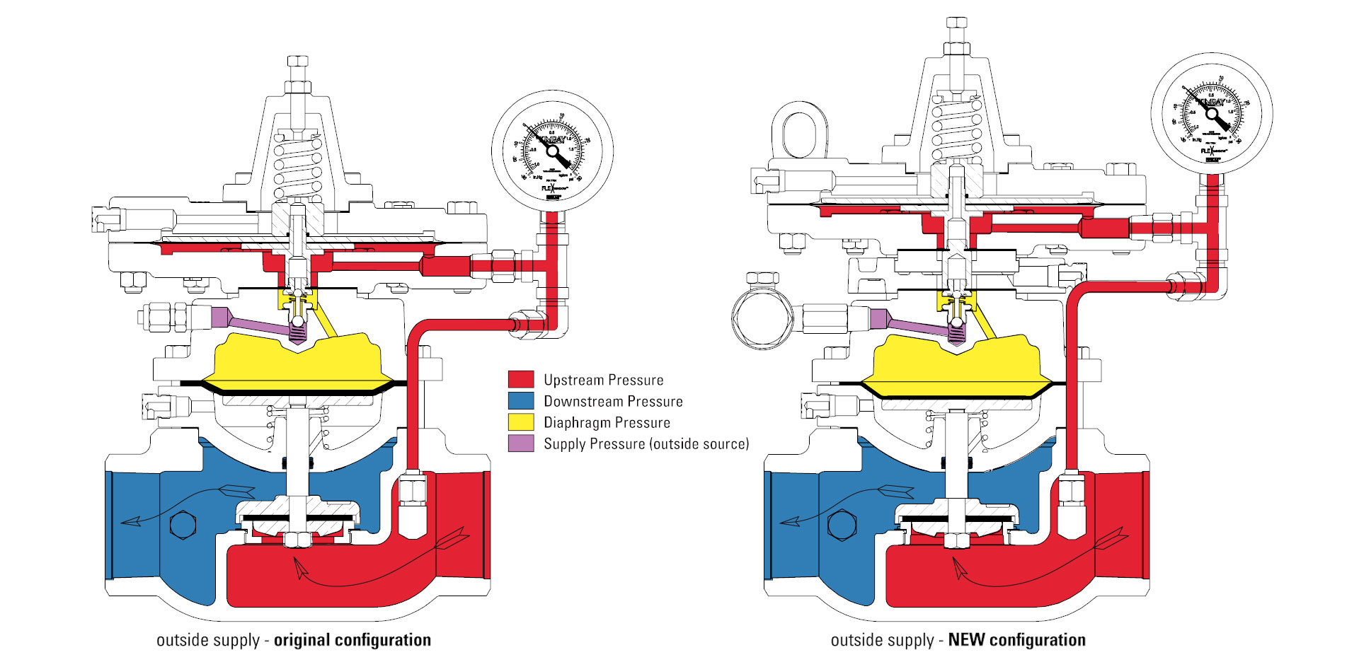
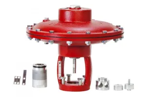
The improved design includes a safety redundancy to prevent potential mixing of process gas and outside supply gas.
This valve can be purchased new, but in this video, we’ll walk through how to convert a low pressure back pressure regulator or low pressure back pressure to atmosphere regulator to the new, safer outside supply configuration.
Conversion Process
For this conversion, first we’ll show how to disassemble the Low Pressure Back Pressure Regulator and then the slightly different process for the Low Pressure Back Pressure to Atmosphere Regulator.
The assembly process will be the same since they will both be an LPBPOS in the end.
In this video, we will only be showing the process using the conversion kit and not a Master Repair Kit. However, the conversion kits do include many commonly replaced components that will be exposed during this targeted disassembly process.
If you intend to complete this conversion at the same time of a reactive, preventative, or predictive maintenance event, it is recommended to use a Master Repair Kit which will include additional diaphragms, packing and O-rings not included with the conversion kits.
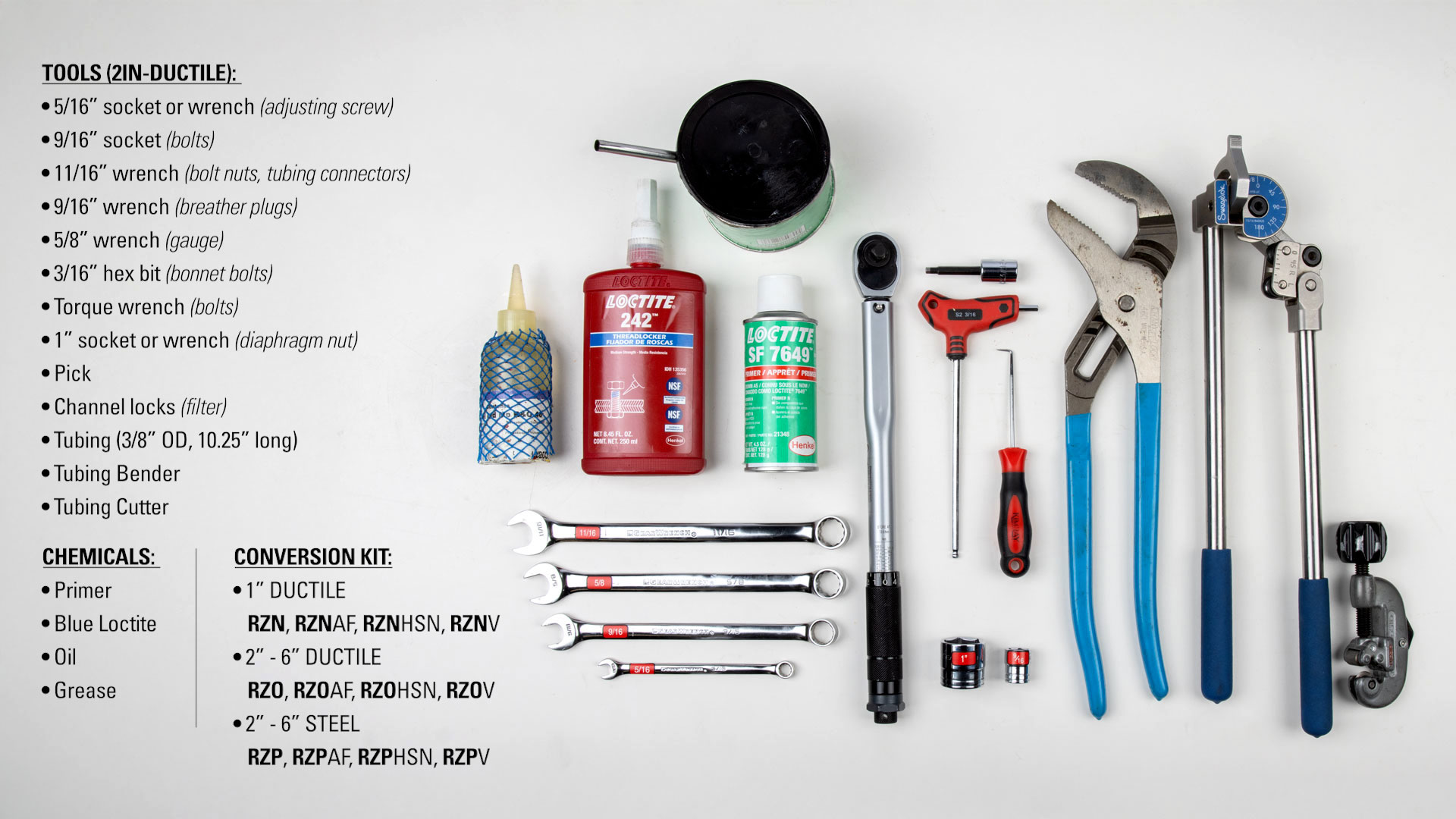
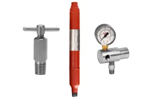
For this process, you’ll need the following tools, components and chemicals:
Tools:
- 5/16” socket or wrench (adjusting screw)
- 9/16” socket (bolts)
- 11/16” wrench (bolt nuts, tubing connectors)
- 9/16” wrench (breather plugs)
- 5/8” wrench (gauge)
- 3/16” hex bit (bonnet bolts)
- Torque wrench (bolts)
- 1” socket or wrench (diaphragm nut)
- Pick
- Channel locks (filter)
Tubing:
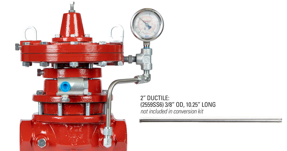
- 2” Ductile: 2559SS6, 3/8” OD, 10.25” long
- Tubing Bender
- Tubing Cutter
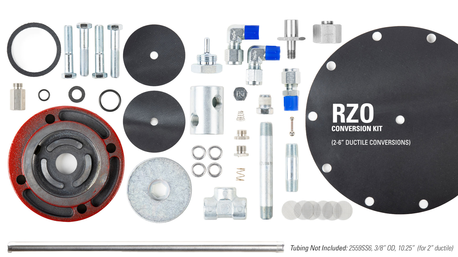 Conversion Kit:

- 1” Ductile: RZN, RZNAF, RZNHSN, RZNV
- 2”-6” Ductile: RZO, RZOAF, RZOHSN, RZOV
- 2”-6” Steel: RZP, RZPAF, RZPHSN, RZPV
Chemicals:
- Primer
- Blue Loctite
- Oil
- Grease
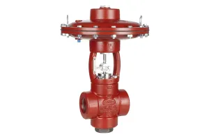
LPBP (a.k.a. OBP) – Disassembly
- To begin disassembly of the LPBP, first, use a 5/16” socket or wrench to remove the adjusting screw.
- Next, remove the gauge with a 9/16” wrench.
- Use an 11/16” wrench to loosen the tubing connectors and elbows.
- Then remove the tubing followed by the elbows.
- Remove the filter by loosening the (648) connector with a 5/8” wrench.
- Next, remove the bonnet by unthreading the six bonnet bolts with a 3/16” hex bit.
- Remove the spring plate and spring.
- Then, remove and discard the (1216) gasket. It may be in the housing or stuck to the bonnet.
- Remove the diaphragm nut with a 1” socket wrench.
- The O-ring may be stuck on the stem or it may come off with the nut. Either way you can remove and discard.
- With a 9/16” socket and an 11/16” wrench remove the bolts and nuts holding the pilot housings together.
- Remove the upper pilot housing.
- Then remove the diaphragm plate.
- Next, remove and discard the (1212) diaphragm.
- Remove the lower diaphragm plate.
- Then remove and discard the four bolts and washers with a 9/16” socket wrench. Longer replacement bolts are included in your conversion kit.
- Remove the lower pilot housing, stem, and pilot seat assembly.
- Remove and discard the (566) booster spring. We’re using a 20 lb. actuator spring in the bonnet; however, if you change this, you will need an additional spring that goes underneath the diaphragm plate. Adding this spring will require additional disassembly of the valve stem assembly.
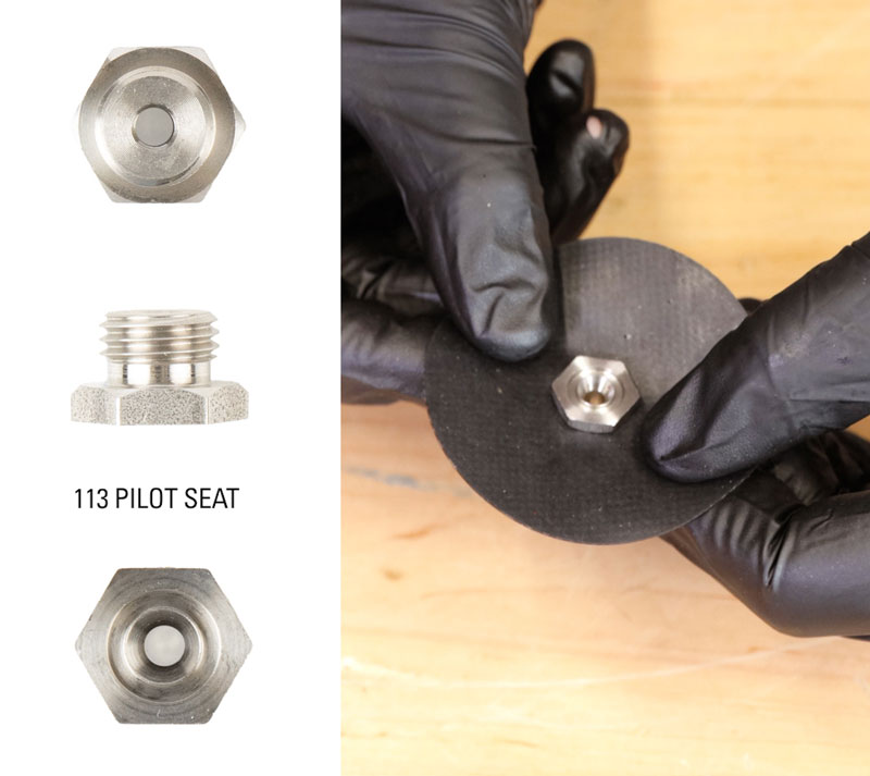
- Remove the (113) pilot seat with a 9/16” socket. Discard the seat and the attached gasket.
- Remove the breather plug from the upper housing with a 9/16” wrench.
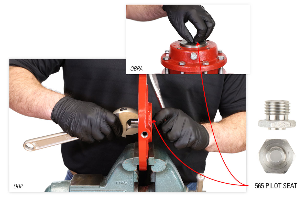
To separate the stem and seat, put the lower housing in a vise. Use an adjustable wrench on the stem hex and a 9/16” socket on the pilot seat.
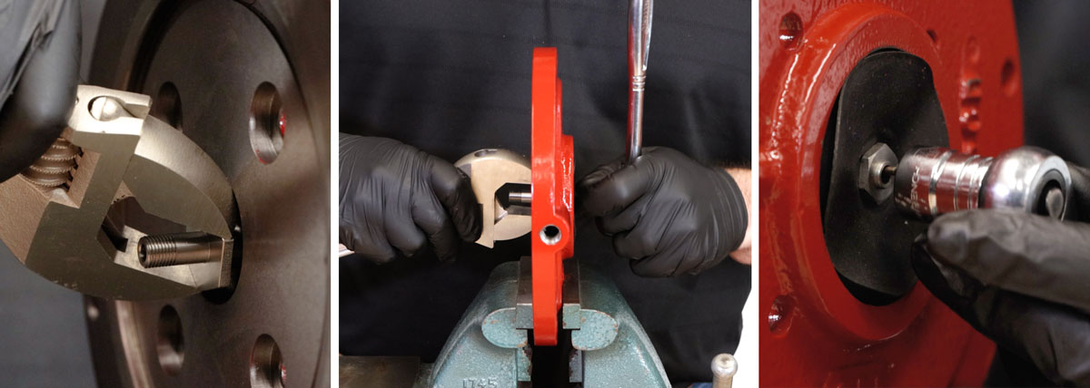
- Discard the stem, (1360) spring, (565) seat, (112) pilot plug, and (110) diaphragm.


OBPA - Disassembly
There are only a few differences for the OBPA disassembly.
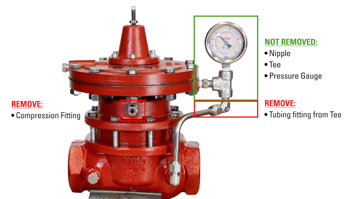
- The main difference is that the (648) nipple, (219) Tee, and (7704) pressure gauge do not need to be removed from the lower pilot housing. Only the tubing fittings need to be removed from the Tee.
- Instead of a breather plug, you’ll remove the (874) compression fitting from upper housing
- Once you separate the stem and seat, the pilot seats will be reversed from the OBP model. This does not impact the disassembly process; it will just look a little different.
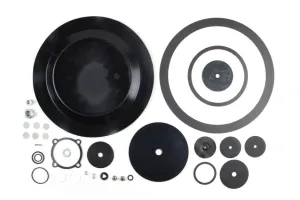
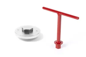
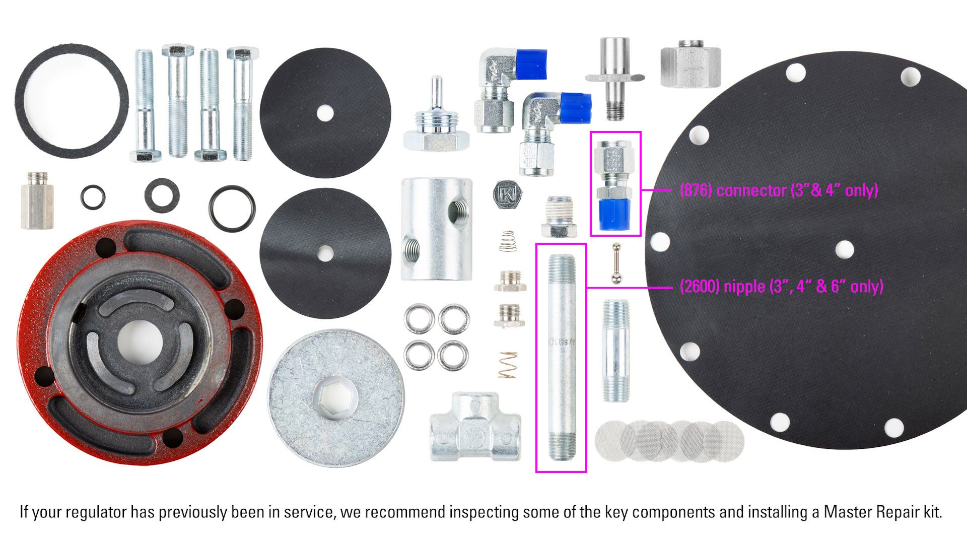
Inspection
With our regulator disassembled, we’ll open the conversion kit to prepare for assembly. If your regulator has previously been in service, we recommend inspecting some of the key components and installing a Master Repair kit.
LPBPOS Assembly
Now we’ll begin assembly of the outside supply configuration.
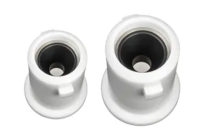
Pilot House Assembly
- Install the (110) diaphragm onto the (113) pilot seat.
- Then the second (110) diaphragm onto the (4297) seat extension.
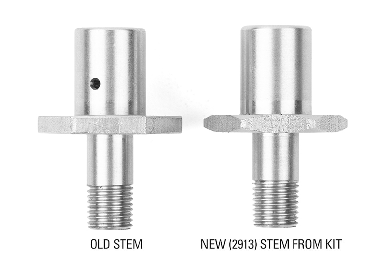
Place the new (2913) stem into a vise with the female threaded end facing up.
- Place the lower pilot housing onto the stem.
- Thread the (4297) seat extension into stem by hand before fully tightening it with a 9/16” wrench. Do not overtighten.
- Position the (2021) spacer ring around the seat extension. The smaller diameter side of the spacer ring will be facing down.
- Install the (1701) pilot housing on top of the spacer ring, smooth side facing up.
- Hand start the (113) seat into the (4297) seat extension before fully tightening it with a 9/16” wrench or socket. Do not overtighten.
- This assembly should have play in it when removed from the vise.


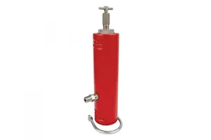
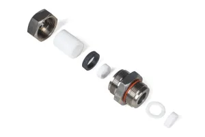
Filter Assembly
- With the (616) filter body in a vise, insert the six (619) filter screens. Use a pick or small flathead screwdriver to push them into place.
- Install the (155) O-Ring onto the (617) filter cap.
- Lightly apply oil to the O-Ring and install the filter cap onto filter body with an adjustable wrench.
- Apply primer and blue Loctite to one end of the nipple connector.
- Hand thread one end of the nipple connector into the NPT port closest to the filter cap.
- Remove the filter from the vise and replace it with the valve body.
- Apply primer and blue Loctite to the other end of the nipple connector.
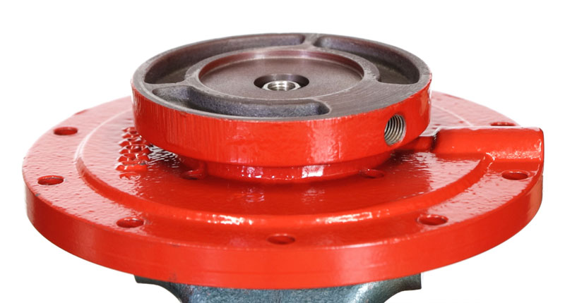
- Hand thread it into the NPT port in the regulator upper housing.
- Fully tighten the filter assembly into the upper housing using an adjustable wrench or channel locks. Orient the filter so that filter cap faces upstream.
- Install the (699) plug with a 5/8” socket or wrench into the bottom port of the filter body.
Pilot Seat & Upper Housing
- Install the (1360) spring into upper housing so that the wide end goes down first.
- Install the (118) gasket onto the (565) pilot seat.
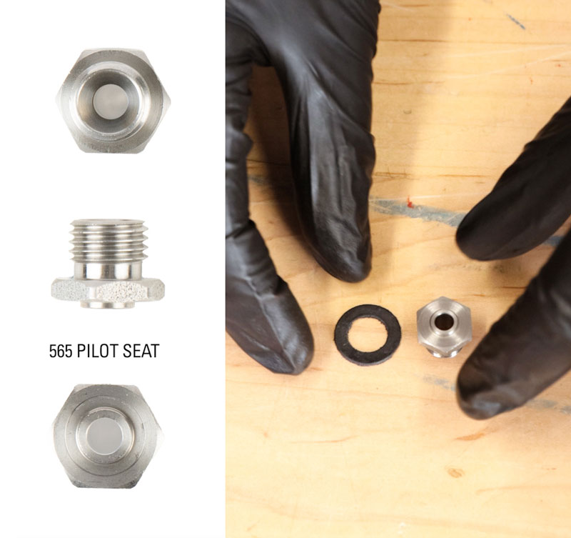
- Insert the (112) pilot plug through the seat, small end first.
- Then, holding onto the small end of the pilot plug, position the seat into the upper housing. Start by hand and then fully tighten with a 9/16” socket. Do not overtighten.
- Place the (566) booster spring on the seat.
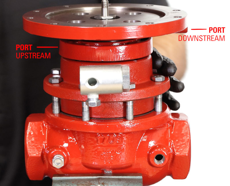
- Place the pilot housing assembly on the upper housing, aligning the port to face downstream and the lower pilot housing port to face upstream.
- Install a (242) washer onto each of the (965) bolts. The smooth side of the washer should be facing the bolt head. These bolts will be longer than the ones that originally came out of the regulator. This extra length is required due to the additional pilot housing components that were added to the design.
- Insert the (965) bolts through the pilot housings. Hand start each of the bolts into the threads of the upper housing and then fully tighten the bolts to 20 ft/lbs.

Connector, Tee & Gauge
- Apply primer and Loctite to the connector.
- Install the connector into the lower pilot housing NPT port with a 5/8” wrench.
- Apply primer and Loctite to the other end of the (648) connector.
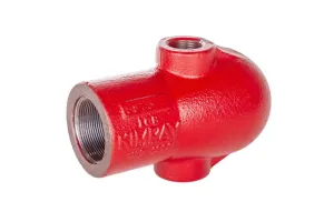
- Install the (219) Tee onto the (648) connector. Once the Tee is tight, orient it vertically.
- Make sure the threads on the gauge are clean, then apply primer and Loctite.
- Install the gauge into the Tee with a 9/16” wrench.
Lower Pilot Housing, Upper Pilot Housing & Bonnet
- Install the lower diaphragm plate.
- Then the (1212) diaphragm.
- Followed by the upper diaphragm plate.
- Place the (265) O-Ring on the stem and apply grease.
- Thread on the (2912) diaphragm nut and then torque to 60-70 in-lbs with a 1” socket.
- Install the upper pilot housing oriented so that the NPT port faces downstream.
- Then install the bolts and nuts to secure the upper pilot housing to the lower pilot housing.
- Grease the surface where the gasket will go, then install the (1216) gasket and grease it too.
- Put the spring and spring plate on the diaphragm nut, ensuring the pivot side of the plate is facing up.
- Lightly grease the pivot on the spring plate.
- Put on the bonnet and start the screws by hand before fully tightening in a crisscross pattern to15 ft-lbs. with a 3/16” hex bit.
- Install the (147) breather plug with a 9/16” wrench, making sure the hole is facing down.
- Finish by installing the adjusting screw into the bonnet with a 5/16” wrench.

Tubing & Elbow Connectors
- The last step we’ll do is bend the tubing to connect the Tee to the upstream NPT port on the valve body.
- Apply primer and Loctite to the threads of one of the elbow connectors and hand start it into the upstream NPT port on the body. It should be vertical with the tube fitting facing up.
- Apply primer and Loctite to the threads to the other elbow connector and then hand start it into the bottom port of the Tee connector. It should be facing the other elbow connector. Do not fully tighten these elbows; we will do this after the tubing is installed.
- Use a scrap piece of tubing in the upstream NPT port elbow as a reference. Position the new tubing in the tee elbow. Mark the tubing at the intersection point.
- Using this mark, use a tube bender and make a 90° angle.
- Place the tubing back into the elbow on the Tee. Line up the other end of the tube with the connector on the body. Mark the tubing at the appropriate cut location. Use a tube cutter to cut off excess length.
- With the tube inserted, lightly tighten the fitting to crimp and position the ferrule components onto the tube. This will make it easier to guide the tubing into it.
- With the finished tubing in place in the upstream NPT port elbow, adjust the Tee elbow so that tubing can be guided in.
- Lastly, fully tighten the fittings.

This completes the conversion. If you have any questions about this process, conversion or repair kits, contact your local Kimray store or authorized distributor.