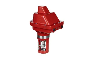
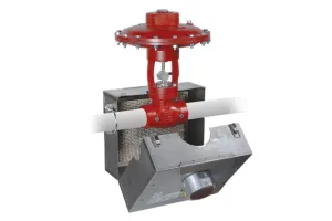


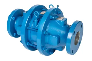


The Kimray R2L Valve Package featuring the Valvcon Electric Actuator is a smart, durable, and cost-effective solution for zero-emission valve control. In this video and guide we demonstrate how to install and calibrate a Valvcon Electric Actuator.
How to Calibrate the Valvcon Electric Actuator
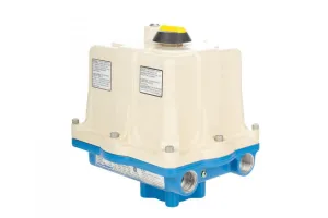
Installation– Mounting & Wiring
- Mount the Valvcon actuator to the R2L Adapter with the included bolts.
- Then remove the cover with a hex wrench. As you remove the cover, be careful to keep it aligned with the base. Many times the manual override comes off with the cover, and the stem can damage the electronics on the back of the board.
- Make sure your limit switch is on the smart mode selection.
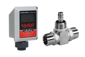
- Terminate 24-volt power to terminals 19 and 20. The Valvcon has universal power capabilities but in the video we set it up with 24 VDC and control it with a 4-20mA analog signal.
- Next, connect the 4-20mA loop calibrator to terminals 15 and 16. We’re using an analog signal, but it also has MODBUS and discrete signal capabilities.
- Turn the on/off control mode selector switch all the way clockwise to the analog setting.
- Set your position control switch on the 4-20 mA setting.
- Turn your operation mode selector switch all the way clockwise to the calibrate setting.
- Now use the clockwise button in the manual control section to drive your stem closed.
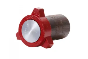
- Once the stem from the R2L adapter makes contact with the valve stem, you can install the coupling block.
- Then remove the rubber clamp and the battery before calibrating.
Calibrating– Cams & Limit Switches
- Use the clockwise and counterclockwise buttons to drive the valve fully closed and fully open to ensure that none of the cams are making contact with the limit switches behind the control board. If a cam contacts a limit switch, the switch trip LED light will appear.
- Loosen the set screw on the cam and retighten it in a spot where the valve can have full travel without making contact with the limit switches.
Calibrating– Potentiometer
- Now we’re ready to calibrate the potentiometer. Use your clockwise manual control button to drive the actuator fully closed.
- Hold the enter button for 2 seconds until the calibrate LED light starts to blink.
- Loosen the set screw on the main gear behind the control board and slowly rotate the main gear clockwise while watching the calibrate LED light. The LED light will blink faster and faster as you get closer to calibration point.
- When the calibration LED is solid, tighten set screw on the main gear.
- Then push the enter button.
- With the potentiometer calibrated, you can now replace the battery.
Setup– Smart Limits
- Next, we’ll set the smart limits. Turn your operation mode selector switch to the zero setting.
- Hold the enter button down for 2 seconds until the LED starts blinking.
- Run your valve to the fully closed position.
- Now send a 4mA signal to the actuator from your loop calibrator or your PLC.
- Push the enter button to lock in your fully closed signal.
- Now, move your operation mode selector switch to the SPAN setting and hold down the enter button for 2 seconds until the LED is flashing.
- Use the counterclockwise button to manually drive the valve fully open.
- Send a 20mA signal the actuator from your loop calibrator or your PLC.
- Push the enter button to lock in your fully open signal.
Calibrate– MID Setting
- If you want the actuator to have a different fail position than fully open or fully closed, you can calibrate this by using the MID setting and following the same process as you did for closed and open.
Setup– Power & Signal Fail Controls
- Now that the valve is calibrated and ready to run, you want to set your power fail and signal fail controls. Signal fail can be set to fully closed, fully open, or last position before losing signal.
Troubleshooting Installation and Calibration Issues
Signal Loss
If control signal to the actuator is lost but external power is still applied, the Signal Fail position selector switch provides options for the actuator: Zero, which is 4mA, Span, which is 20mA, or Last, which is the position the valve was in when the signal was lost.
Power Loss
The Valvcon actuator is also equip with a back-up battery. If power to the actuator is lost, the Power Fail controls switch provides options for the actuator: Clockwise, in which case the valve will drive fully closed; Counter-clockwise, in which case the valve will drive fully open; or MID, in which case the valve will drive halfway between open and closed.