
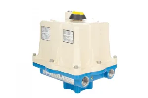


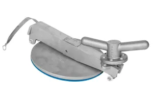


The Kimray Electric Actuator is designed for producers who want to automate their control valves without overcomplicating their processes. Electric controllers in energy production are becoming widely used, and they introduce new scenarios that operators may be less familiar with than pneumatic or mechanical devices.
In this video, we’ll go over a few steps you can take to use the tools built into the Kimray Electric Actuator to better understand what’s happening and help problem solve common issues you may be facing.
- The Actuator Is Having Trouble Calibrating
- The Electric Actuator is Calibrated but Not Moving
- On Start Up, the Screen Displays “No Encoder”
The Actuator Is Having Trouble Calibrating
If your Electric Actuator will not calibrate, here are some system checks to figure out what may be happening.
VIN+/- LED
The first indicator you can check, which often gets overlooked, are the LEDs on the circuit board. On the VIN+/- a green LED shows the status of the input voltage.
- A solid green LED indicates the VIN is present.
- A flashing green LED means you’re running on the battery backup, which still means you are not getting a sufficient voltage.
- No LED means you are getting insufficient voltage for the default factory settings, which is under 17V.
For a 24V application, 21V is the minimum voltage required. If the LED is either flashing or not on at all, the next step will be to check your Voltage IN in the system health menu.

SYSTEM HEALTH Voltage IN
From the main operating screen, press RIGHT until you see SYSTEM HEALTH. Press DOWN to enter the menu.
Scenario 1: Operating a 24V System, but Actuator Is Showing a Lower Voltage
If you know your system is using 24V but the read out is showing lower, this means there’s a problem in the system somewhere else and not with the actuator.
The typical problem here is that the wire size is too small. For longer wire runs, be mindful of voltage drop at higher currents. To supply 24V power, use 12-gauge wire size for 100’ of cabling. If you need more distance, you will begin to lose voltage because you cannot increase your wire gauge as the maximum wire size you can use for the electric actuator is 12-gauge.
If the distance is too great, the power supply may possibly need to be relocated.
At this point, we can likely assume the actuator is working as expected, but the voltage is insufficient. You’ll need to take site-specific steps to address the voltage issue.
Scenario 2: Operating a System Less Than 24V
The electric actuator was designed to run at 24V; however, if you know your system is not setup for that voltage, you can lower the parameters on the actuator but will lose battery backup capabilities and a calculated amount of torque and speed in the process. This is not typically recommended, but if your application allows these losses, here are the steps to lower the voltage input on the electric actuator.
- UNPLUG BATTERY
- First, unplug the battery as it will not charge with less than 17V.
- REDUCE VIN MIN.
- From the main menu, press RIGHT until you see FAIL MODE SETUP.
- Press DOWN to select.
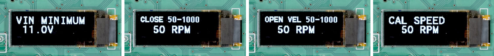
- Press RIGHT until you see VIN MINIMUM.
- Press DOWN until you reach 11V, which is the minimum voltage the actuator will function.
- Press RIGHT to accept the input.
- Press LEFT until you see the main operating screen.
- REDUCE VELOCITY
- From the main menu, press RIGHT until you see VALVE SETUP.
- Press DOWN to select.
- Press RIGHT until you see the OPEN VELOCITY menu.
- Press DOWN to reduce this to 50 RPM.
- Press RIGHT and it will display close velocity. Reduce this to 50 RPM also, and then press RIGHT to accept.
- Press LEFT until you see the main operating screen.
- CAL SPEED
- From the main menu, press RIGHT until you see CALBIRATION MENU.
- Press DOWN to enter the menu.
- Press DOWN to set CAL SPEED to 50RPM.
- Press RIGHT to select this value.
- Press LEFT until you see the main operating screen.
If you’ve walked through these steps and the actuator is still not calibrating, contact our Kimray Customer & Product Support Team for further assistance.
The Electric Actuator is Calibrated but Not Moving
If the problem you’re facing instead is that the Electric Actuator is not moving after calibration, try the following steps.
LEDS
First, check the LEDs on the circuit board. This was explained in the previous section but again is often overlooked and a simple way to begin diagnosing. This time, check the analog input (AI+/-).
- On the AI+/- a solid green LED indicates that loop voltage is being provided by the external controller.
- If there is no LED light and you know you are sending a 4-20mA signal, this means something is wrong on the analog side of the process and not with the actuator.
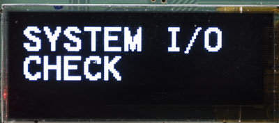
SYSTEM I/O – Calibration Status
Next, check the System I/O. To get to this menu from the main operating screen, press RIGHT until you see SYSTEM I/O, then press DOWN to enter the menu. Press RIGHT until you see the graph.
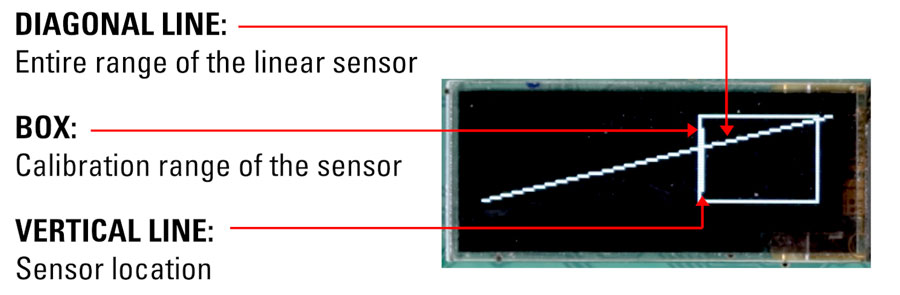
The calibration status is displayed as a graph.
- A diagonal line represents the entire range of the linear sensor.
- A box shows the calibration range of the sensor.
- A vertical line shows where the calibrated range of the sensor is.
If the vertical line is inside the box, in any location, calibration was successful. If it appears outside of the box, press the UP button to put the valve into manual adjust mode.
Now use the UP/DOWN buttons to reposition the valve to see if the vertical line will move with stem position. Continue to rotate the spindle until the valve is fully open. The new position of the vertical line does not necessarily need to be within the current calibration range box.
Hold down the RIGHT button to change the calibration so that the current position becomes the new 100% open position.
If resetting the calibration range does not resolve the issue, call Kimray Customer & Product Support for further assistance.
SYSTEM I/O – ANALOG INPUT
Next, use the System I/O menu to verify that you have a mA signal in the analog input.
- From the main operating screen, press RIGHT until you see SYSTEM I/O.
- Press DOWN to enter the menu.
- Any display between 4-20mA means the analog IN is operating correctly.
- If this displays 0mA, that means the analog signal is not being received. There could be an issue with the connection or with the device that should be sending a signal to the actuator.
- If there’s no mA signal, that means that there’s a problem elsewhere in the system, not on the Electric Actuator.
- Check to make sure your wire is sized correctly and is an appropriate length to minimize amperage loss.
- There could also possibly be interference with other devices if the cable is not shielded.
If you’ve proven that the actuator is getting a signal but is still not moving, contact Kimray Customer & Product Support for assistance.
On Start Up, the Screen Displays “Encoder ERROR” or "No Encoder"
Simply put, the encoder detects stem travel. If the screen displays ENCODER ERROR, there is likely an error with the encoder wiring.
- First, remove all power from the actuator.
- Then inspect for disconnected or damaged wiring from the encoder to the terminal block. Depending on the damage, it may need to be replaced. Call your local Kimray store for the next steps.
If the screen displays NO ENCODER, you will need to reset the Electric Actuator.
- First, unplug the battery connector.
- Remove power to the board and wait 10 seconds.
- Re-connect the power supply and plug in the battery.
- Navigate to the Encoder Status menu. From the main operating screen, press RIGHT until you see SYSTEM I/O, then press DOWN to enter the menu. Press RIGHT until you see Encoder Status.
- If the screen shows ENCODER GOOD, the problem has been resolved.
- If it still displays NO ENCODER, the sensor or control board will need to be replaced by your local Kimray store.
If at any time you still need assistance, reach out to the Kimray Customer & Product Support team to walk through your scenario with a team member today.