Recently I visited a customer's operations in west Texas. The challenges we encountered there - including valve placement and well slugs - were very common. Therefore, I thought I would take a minute to share the findings in case it's helpful to other producers.
The customer had been using Kimray control valves and equipment for the life of this site. Their field operators were reporting some production issues, so we set up a visit. The goal was to observe their set up, help them troubleshoot, and offer insights on how they could run more efficiently. Here were our findings:
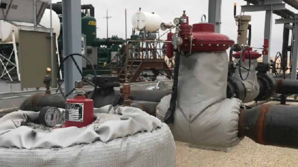
Back Pressure Valve on Flare
The field had concerns about a back pressure valve being able to react quickly enough to adjust to inbound gas slugs from production. Furthermore, often their flow rate could vary from 100MSCFD-15MMSCFD at a 15-20 PSI differential. Therefore, the valve had to be able to unload quickly. It also had to handle the potential well slugs in the gas process piping from the separator. Liquid presence in the gas pilot-operated back pressure valve causes erratic set points and improper functionality.
Based on their particular conditions and flow rates, we presented them with two options to address this:
Option 1: Change Valve Placement
The first option addressed the placement of the back pressure valve. We suggested moving the valve from the inlet piping of the flare knockout to the outlet piping. This would allow the flare knockout to collect all liquid present in the gas outlet piping from the production separator. Operationally, the knockout would maintain the same amount of back pressure as previously set on the upstream side of the valve.
This recommendation only addressed the problems caused by liquid being present in the sensing line or diaphragm area of the valve. Furthermore, we felt this could be enough change that the valve could position quickly enough to handle the changes in flow rate.
Option 2: Replace with Electric-Operated Valve
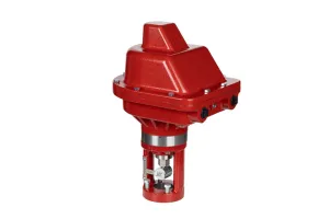
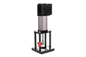
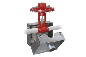
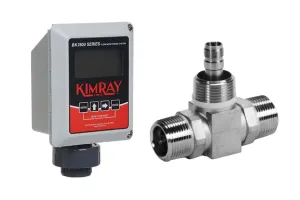
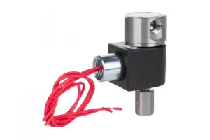
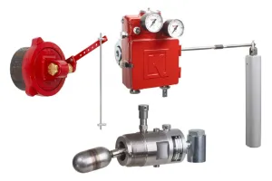
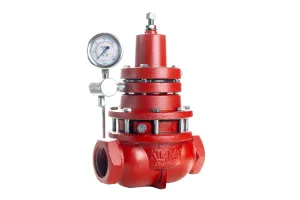
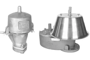
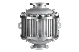
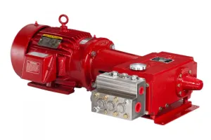
Replacing the gas-operated pneumatic valve with an electric-operated valve would address both the speed concerns, as well as the liquid presence in the gas outlet piping (see Figure 1).
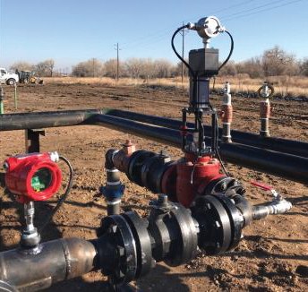
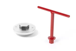
Figure 1
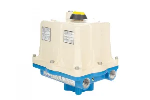
The Kimray products shown in Figure 1 represent part of our electric product line. On the far left is our Electric Pilot. This is controlling a 3” full port control valve with our Tritex II Electric Actuator. The Tritex II actuates at a speed up to 5”/sec. This solution would address the problem of liquid in the gas piping as well as the speed of operation.
Our new Electric Pilot (releasing in April, 2018) facilitates the valve control. Also, it operates independent of any existing PLC or RTU system. This system requires 12-48VDC power and can be run off of solar power primarily. Furthermore, remote communications can be run back to existing ModBUS/Radio from the Electric Pilot. Position feedback and set points can be viewed and changed remotely.
IPR Outpace Valve Capacity with Well Slugs
A second issue brought up also involved well slugs. Slugging wells cause high-level alarms to trip once a production separator can no longer dump liquids quickly enough. This further contributes to the problem discussed above. That being liquid presence in the gas outlet piping and instrumentation.
To address this problem we decided to size the customer's present conditions considering slug rates. Our thought was that control valve design choice may be prohibiting full flow, therefore limiting the amount of fluid that could be passed through the valve. Two options that would allow handling of the increased flow would be:
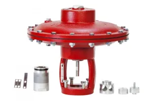
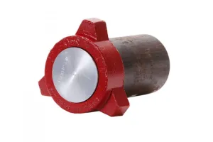
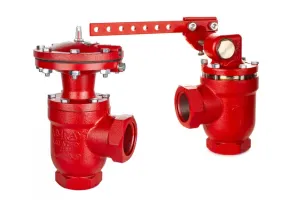
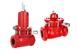
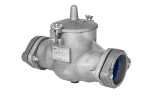
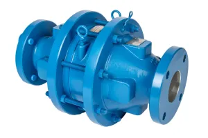
Option 1: Change Control Valve Design
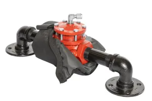
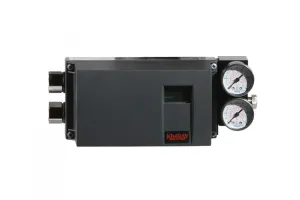
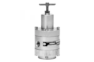
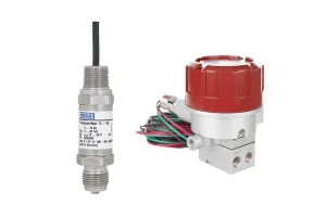
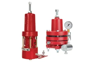
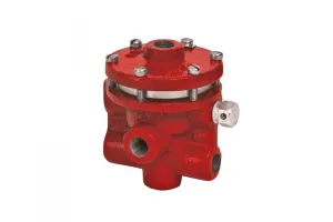
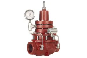
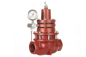
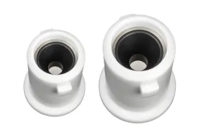
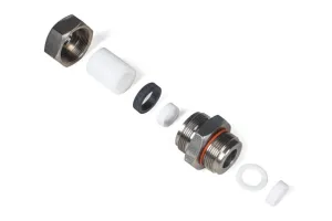
Changing the valve design to accommodate for a full port valve would allow for the needed flow. Figure 2 shows their valve design capacity (Cv Value = 43.8), and Figure 3 shows the recommended valve design capacity (Cv Value = 89).
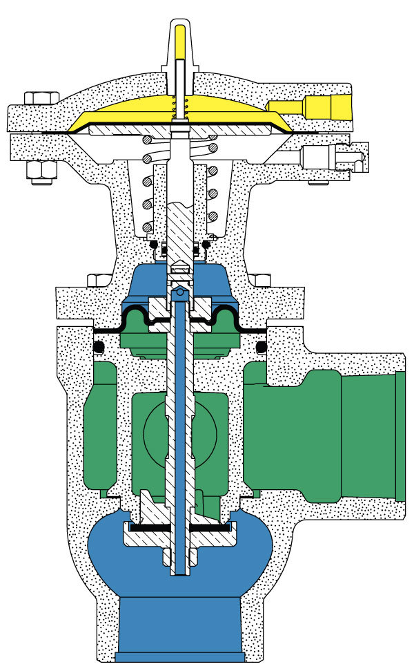
Figure 2
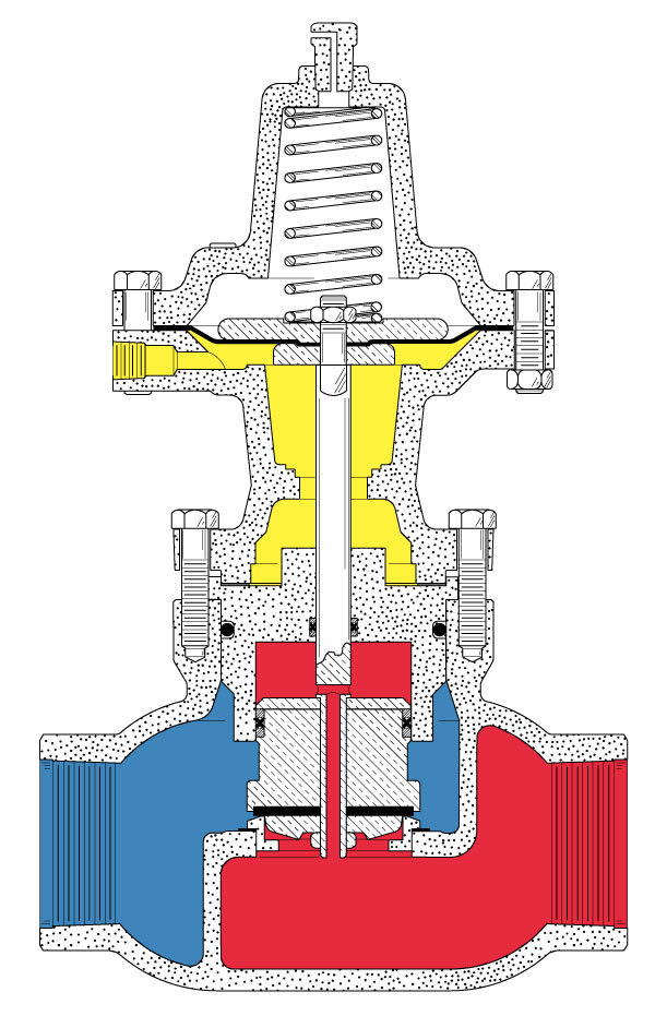
Figure 3
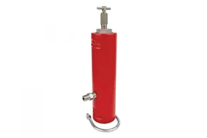
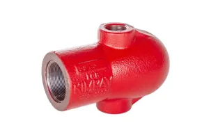
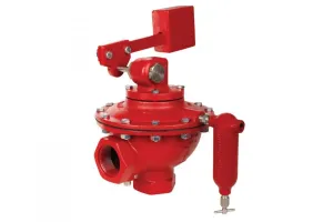
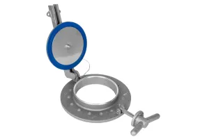
Option 2: Add a Secondary Valve
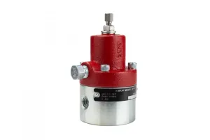
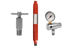
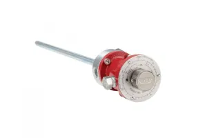
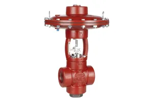
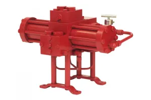
The other option would be adding a secondary valve that would be opened by a signal from the high-level switch. Figure 4 illustrates the second option of installing a solenoid valve on the supply gas inlet to a second dump valve for additional flow. PN YDF is the 110V model, and PN YDF1 is our 24V offering. Both models are normally closed solenoids with 1/4” NPT connections and come standard with an explosion-proof-rated housing.
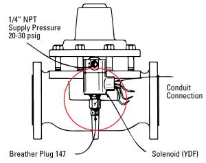
Figure 4
Conclusion
With these adjustments, we anticipate this field is going to see increased efficiency and avoid downtime due to wet gas issues and slugging wells.