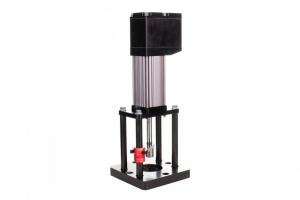
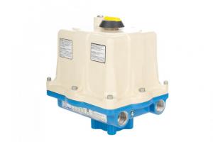
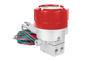
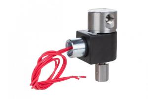
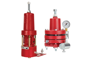
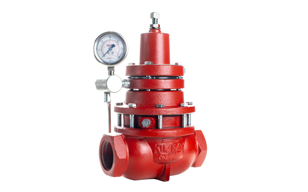
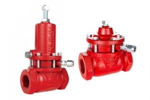
The Kimray Electric Low Pressure Control Valve (E-Lo) is designed primarily to control flow of low pressure (<45 PSIG) fuel gas within burner management systems.
How to Replace a Module and board on the Electric Low Pressure Control Valve
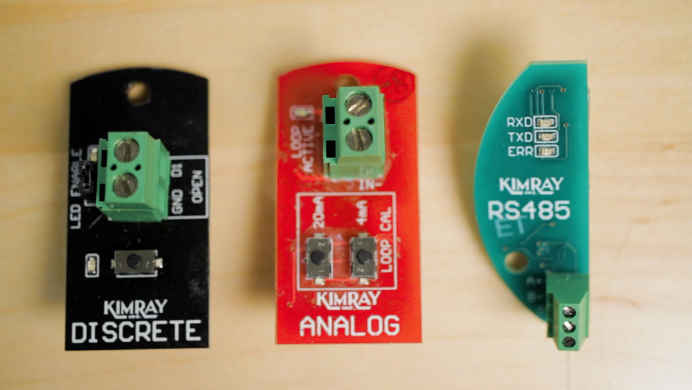
The E-Lo utilizes a main circuit board and one of 3 module options:
- a discrete module, which uses dry contacts only and less than 3 volts;
- an analog module, which is 4-20 milliamps for variable control;
- or a Modbus control module which can be utilized with Modbus RS-485.
These modules can be changed out to suit your application needs, but it is ESSENTIAL that you turn off all power before doing this or any other work to the E-Lo.
Because it is run on low voltage (24V), operators may be tempted to wire in the main board or change a module without powering down the unit. This is a big problem for many reasons, including safety and functionality.
These modules are not designed to be “hot swapped” — or swapped out while power is coming in.
Putting a module in while there is power on the unit will almost inevitably damage it. The surge of electricity can fry its memory and result in it not functioning correctly, or perhaps at all.
If you are experiencing performance issues with the E-Lo, like It’s not opening or closing fully, or it’s not responding to an input, the module or main board may have been damaged at some point. If you suspect this is the case, you will likely need to contact your Kimray rep to order a new module or board. You can visually inspect them for damage, though the damage may not always be visible.
Here’s how to replace the module:
- Once the system has been de-pressurized and electricity turned off, remove the cover and disconnect the input wires from the module.
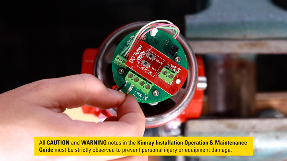
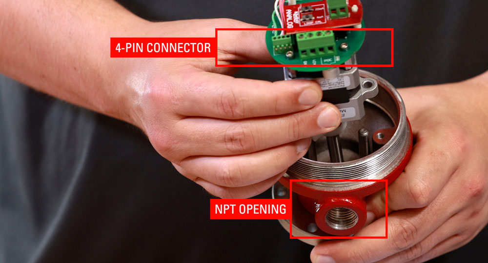
- Now, simply remove the old one, snap the new module in place, and reconnect the input wires. On the board, you will also see a 4-pin connector with the voltage in, ground and a proof-of-closure connection. The POC is for discrete output to an LED or an auxiliary alarm to let you know it’s seated.
- Thread on the cover and you’re finished.
Here’s how to replace the circuit board:
- Once the system has been de-pressurized and the electricity turned off, remove the cover and disconnect the input wires.
- Remove the module if it is in place. Use a control screwdriver and disconnect motor wiring from the board. Remove the four hex bolts with a 3/32” hex key.
- Remove the board and fasten the new board to the unit with four hex bolts.
- Reconnect the motor wiring, replace the module, reconnect the input wires, and thread on the cover.
Preventative Maintenance for the Electric Low Pressure Control Valve (MXC, MXD & MXE)
Preventative Maintenance should be performed on the E-Lo on a regular basis. Under normal conditions, the body will last years; however, you need to inspect the valve seat every 6 months under normal service and conditions.
Under severe service conditions such as sand, corrosion, salt or high pressure drop, inspect more often until a predictable pattern can be established.
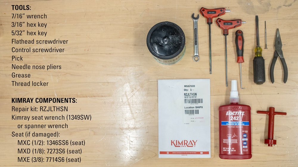
Tools Needed:
- 7/16” wrench
- 3/16” hex key
- 5/32” hex key
- Flathead screwdriver
- Control screwdriver
- Pick
- Needle nose pliers
- Grease
- Thread locker
Kimray Components Needed:
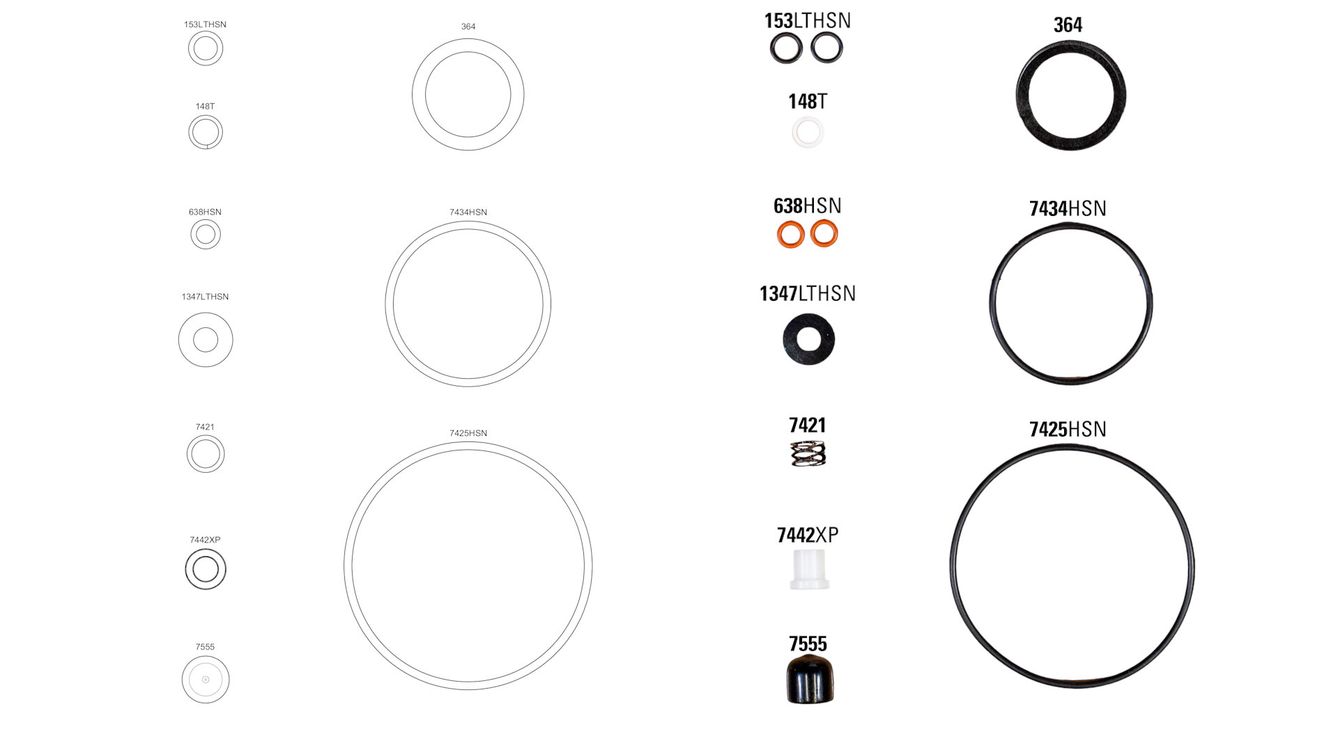
- Repair kit: RZJLTHSN
- Kimray Seat Wrench (1349SW) or spanner wrench
- Seat (if damaged):
Disassembly
- Once the system has been de-energized of pressure and electricity, remove the cover and disconnect the input wires.
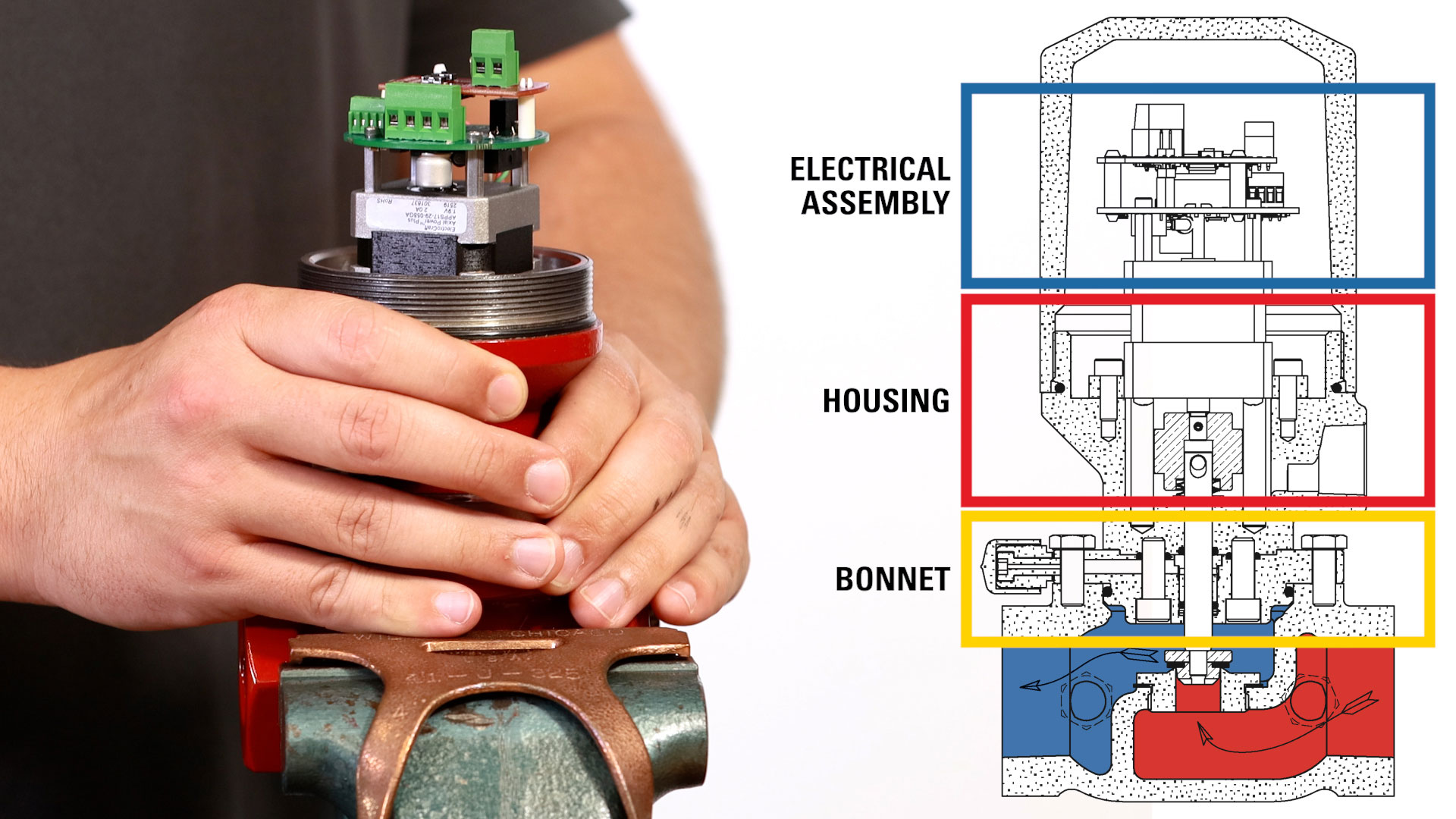
- Remove the (6) bonnet cover bolts with a 7/16" wrench and carefully remove the electrical assembly, housing and bonnet.
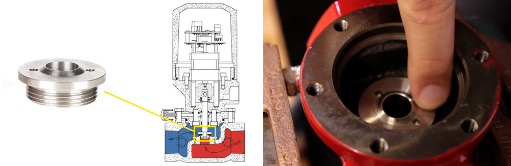
- With a flathead screwdriver, remove the ratio plug and set it aside. Discard the rubber seat and keep the seat disc.
- Flip the unit over and use a 5/32” hex key to remove the 2 screws on the motor flange. If you can’t reach the screws with your hex key, you may need to remove the circuit board as previously shown.
- Separate the motor from the housing by gently pulling the shaft through the assembly.
- Remove the 2 guide pins from the housing.
- Rotate the unit again and use a 3/16” hex key to remove the 2 socket head screws and separate the housing body from the bonnet.
- Use a pick to remove and discard the larger O-ring from the bonnet.
- Push the Teflon back up, O-ring and stem bushing through the bonnet to remove and discard from the other side.
- Use a pick to remove and discard the 2 O-rings from the top of the bonnet.
- From the housing, remove and discard the small O-ring from the bottom and the large O-ring from the threads.
- From the stem, carefully remove the retaining ring using a pick.
- Remove the washer and set it aside.
- Lastly, remove and discard the spring.
Replacing the Seat If Needed:
Inspect the seat for damage. If it needs to be replaced, you will need to order this part separately because it is not included in the repair kit.
- With the Kimray Seat Wrench (1349SW), unscrew the seat from the body.
- Remove and discard the seat gasket. It may be either stuck to the seat or in the body.
- Clean the gasket seating surfaces to remove any residue.
- To reinstall the seat, first install the seat gasket onto the seat.
- Apply grease to the gasket
- Then screw the seat into the body with the Kimray Seat Wrench.
Assembly
- During all parts of the assembly, be careful not to damage the module or circuit board by resting the unit on any surface.
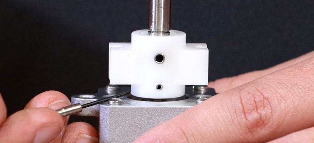
- Before assembling, rotate the stem carrier to leave a gap between it and the motor body approximately 3 full turns from fully seated, or about 1/8”.
- Install the spring and washer onto the valve stem.
- Install the retaining ring next with needle nose pliers. Make sure the stem is pulled out completely to make it easier to install.
- Install the O-Ring on bottom of the bonnet.
- Flip it over, then install the two small O-rings.
- Install the Teflon backup.
- Install the O-ring on top of the Teflon backup.
- Install the stem bushing.
- Apply a small amount of grease to the O-rings and bushing.
- Install the O-ring on the bottom of the housing and apply a small amount of grease.
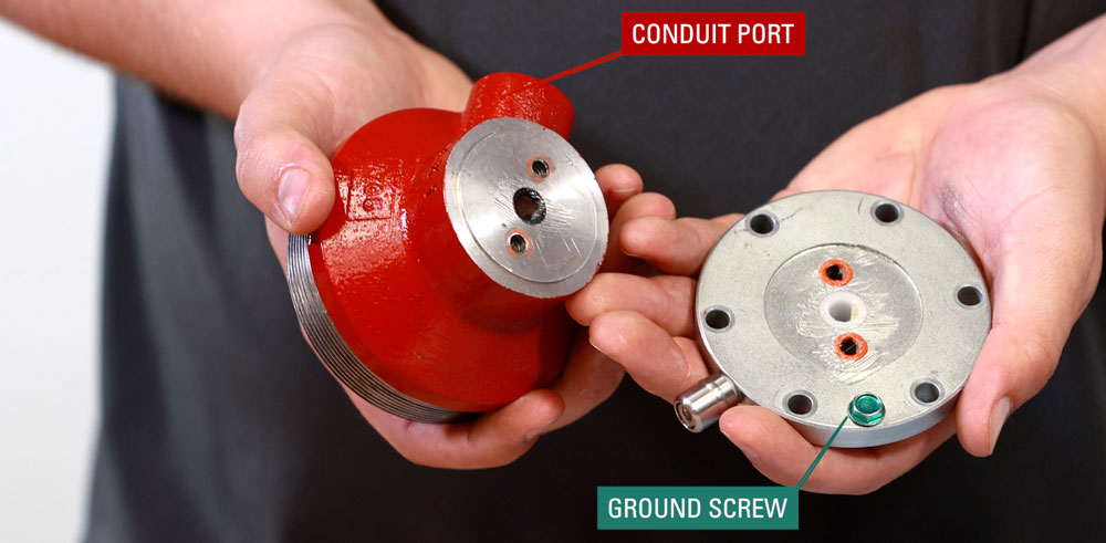
- Align the bonnet and housing. The ground screw should be facing 180° from the conduit port. Secure firmly with two 3/16” hex screws.
- Insert the 2 guide pins into the housing.
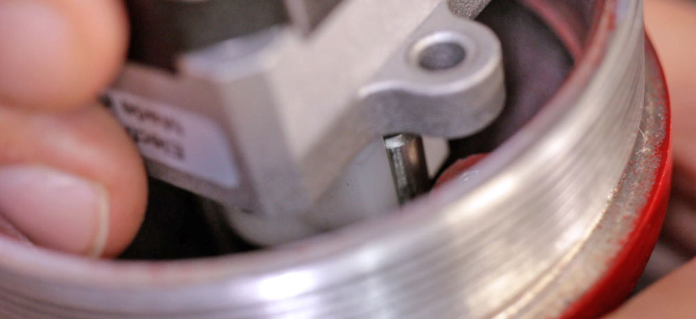
- Insert the valve stem through the housing with the 4-pin connector on the same side as the NPT opening. The stem carrier must be installed between the guide pins.
- Secure the motor assembly with two 5/32” hex screws.
- Apply a small amount of thread locker to the stem threads.
- Install the seat disc (part number towards the bonnet) and new rubber seat.
- Install the ratio plug, making sure the seat is centered before tightening.
- Align the bonnet onto the body with the annunciation stem facing downstream.
- Install the 6 screws in a star pattern and torque to 10 ft-lb.
- Install the large O-ring around the housing threads and apply grease.
- Connect all input wires and follow all setup and test instructions in the IOM.
- Put the new cap over the annunciation stem.
- Thread on the cover until it is firmly seated.
For help with your E-Lo, contact the Kimray Product Support team.