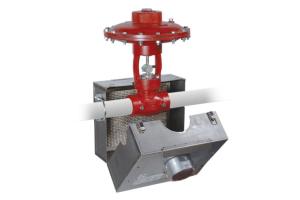
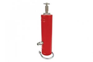

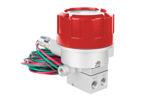
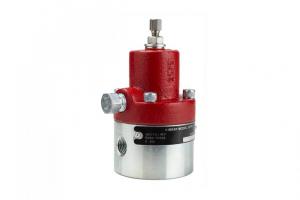
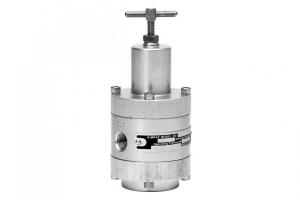
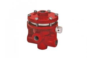
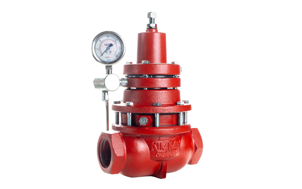
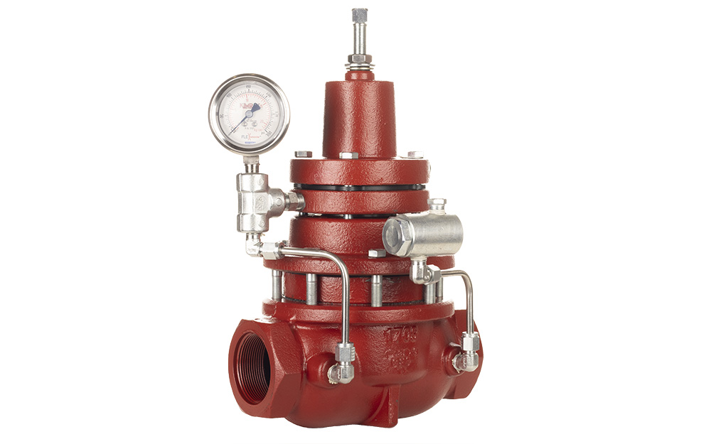
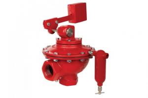
The Kimray Gen 3 Liquid Level Controller is a simple, versatile solution that allows for quick adjustments, intuitive set up, and precise liquid level control.
In this video, Mike shows you how to perform proper maintenance on the Gen 3.
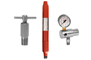
Parts Needed
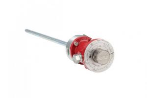
The Gen 3 includes a 1/8" hex key for the pilot and lever fasteners, and it can be conveniently stored inside the enclosure as shown here.
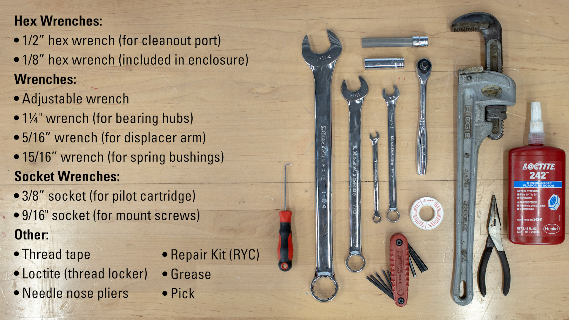
In addition to this tool, you will also need the following:
- Adjustable wrench
- 1/2” hex wrench (for cleanout port)
- 1/8” hex wrench (included in enclosure)
- 1¼" wrench (for bearing hubs)
- 5/16” wrench (for displacer arm)
- 15/16” wrench (for spring bushing)
- 3/8” socket (for pilot cartridge)
- 9/16" socket (for mount screws)
- Thread tape
- Loctite (thread locker)
- Needle nose pliers
- Repair Kit (RYC)
- Grease
- Pick
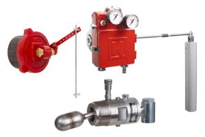
Repair Kit Replacements
Repair kits contain all seals and wear components recommended to be replaced during scheduled maintenance intervals for the entire unit. We recommend an initial maintenance interval of 6 months. This interval can be increased or decreased based on the condition at the time of the first 6-month service.
Most of the following maintenance steps can be performed with the unit still connected to the vessel. But, as with any maintenance being performed, make sure all pressure has been released from the vessel, and confirm that no supply gas pressure remains in the lines or the pilot prior to beginning any maintenance.
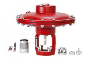
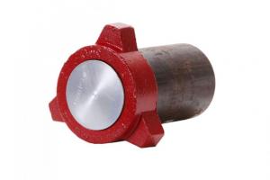
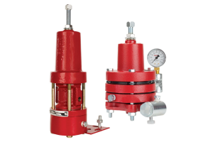
PILOT
A clean and well-maintained pilot is key to the performance of the Gen 3. Wet or dirty supply gas can introduce blockages in pilot communication holes or cause the pilot plug to stick. This can lead to the pilot not sending a signal or venting when it should, or continuously sending a signal.
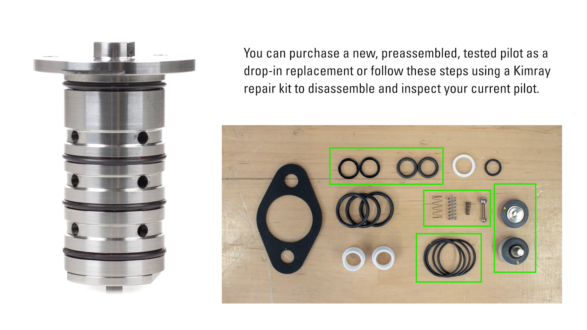
You can purchase a new, preassembled, tested pilot as a drop-in replacement or follow these steps using a Kimray repair kit to disassemble and inspect your current pilot.
- Remove the socket screws with the included 1/8" hex key.
- Then remove the pilot by prying under the flats.
- Remove and discard the four O-rings around the outside of the pilot cartridge.
- Place the flats of the lower pilot cartridge into a vise or hold it in place with a wrench.
- Unthread and remove the flanged top pilot cap with a 3/8" or adjustable wrench.
- Remove and discard the spring.
- Use pliers to remove and discard the upper diaphragm assembly and the conical spring.
- Turn the pilot assembly over to remove and discard the pilot plug.
- Unthread the pilot cap with a 3/8" socket or adjustable wrench.
- Use pliers to remove and discard the lower diaphragm assembly and lower spring.
- Clean out all communication holes. Inspect pilot plug seat area for scratches, scoring, or pitting. If there is damage that could allow a leak path, you’ll need to replace the pilot.
- Place the lower spring on the lower diaphragm assembly and install it into the pilot cartridge.
- Hand start threading the lower cap over the lower diaphragm assembly. Use a 3/8” socket to torque to 25-30 in-lbs.
- Turn the pilot cartridge upright and put it in the vise.
- Install the pilot plug, small diameter ball first, all the way into the seat area so that the large diameter ball rests in the seat.
- Place the small end of the conical spring onto the upper diaphragm assembly. Use needle nose pliers to insert the assembly straight into the cartridge.
- Place the booster spring on top of the diaphragm assembly.
- With the spring centered in the hole, place the top cap on the pilot cartridge. Tighten by hand and torque to 25-30 in-lbs. with a 3/8” socket.
- Remove the cartridge from the vice and install the four O-rings into the narrow grooves on the outside of the cartridge. Then lightly grease the O-rings. CAUTION: Do not allow grease to get into the communication holes, as this could cause the pilot to not operate properly.
- Insert the pilot cartridge into the enclosure, rotating clockwise to avoid unthreading the pilot as it’s inserted into the enclosure.
- Line up the holes in any orientation and install the three socket screws with the 1/8" hex key.
MOUNT (Disassembly)
For this portion of the maintenance, the unit should be removed from the vessel.
- Place the Gen 3 in a vise by the mount only.
- Remove the displacer arm along with any extensions from the mount using a 5/16 adjustable wrench.
- Open and remove the cover.
- Relieve some of the force on the spring by rotating the spring adjusting knob clockwise.
- Remove the spring and upper spring plate.
- Remove the torque lever by loosening the set screw on the underside using the included 1/8” hex key.
- Remove the two mount screws with a 9/16” socket, and lift the enclosure off the mount, leaving the mount in the vise.
- Remove and discard the mount gasket between the enclosure and the mount.
- Remove the first bearing hub with a 1 ¼" wrench.
- Flip the mount over in the vise and remove the second bearing hub and shaft.
- Use a pick to remove and discard the outer O-rings.
- Remove and discard the flanged bearings from both hubs.
- Use a pick to push out the O-ring and back-up ring from inside both hubs. These can be discarded.
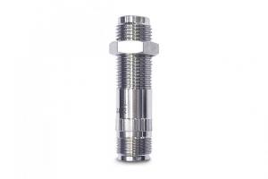
- Remove the access port socket plug with 1/2” hex wrench from the end of the mount.
- Remove and discard the O-ring from threads.
- Inspect the shaft for scoring, pitting or other potential leak paths, especially around the sealing areas.
- Clean out any solids that have built up inside of the mount.
MOUNT (Assembly)
- Install the O-rings over both bearing hubs & the socket plug. Roll the O-ring over the threads instead of pushing them over the threads in order to avoid damaging the seal.
- Start socket plug by hand and tighten to 30-35 ft·lbs.
- In both bearing hubs, stack the O-ring on the concaved side of the back-up ring. Insert the stack, back-up ring side down into the bearing hub and push down until it seats. Turn it over to make sure it’s sitting flush.
- Insert the flanged bearing.
- Install one of the bearing hubs on the back side of the mount. Tighten with a 1 ¼” wrench.
- Flip the mount over in the vise and insert the short side of the shaft into the installed bearing hub.
- Install the second bearing hub over the shaft. Tighten both bearing hubs to 30-35 ft·lbs.
- Use the torque lever as a tool to turn the shaft so that the threaded hole in the middle of the shaft is facing out.
- Apply blue Loctite to the threads of both ends of the displacer arm.
- Thread the displacer arm into the shaft and tighten with a 5/16” or adjustable wrench on the flats.
- If you’re using a vertical displacer, use the coupling to connect it to the displacer arm.
- If you’re using a horizontal displacer, thread the displacer directly onto the displacer arm.
- Align the mount gasket and enclosure over the mounting holes.
- Apply blue Loctite to the mount screws then install.
- Slide the torque lever over flats of the shaft with the set screw facing downward, then tighten the set screw.
SPRING ASSEMBLY
- Remove ½” NPT spring bushing with a 15/16” or adjustable wrench.
- Unthread the spring assembly from the lower spring plate and remove it from the enclosure.
- Remove and replace the spring adjuster washer and O-ring on the spring adjusting knob.
- Thread the lower spring plate on the adjusting knob, then insert the assembly into the enclosure.
- Apply thread tape to the ½” NPT spring bushing and thread it into the enclosure by hand.
- Tighten it fully with a wrench.
- Push down on the lower spring plate firmly until it bottoms-out onto the bushing.
- Lift the displacer arm and install the spring and upper spring plate. Make sure the rounded protrusion aligns with the hole in the torque lever.
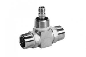
FILTER:
- Remove the filter using an adjustable wrench.
- Clean out the filter element using compressed air in the hole in the male connection end.
- Apply thread tape, then reinstall the filter into the enclosure.
Pilot Lever Washer
- Use the 1/8” hex key to remove the pilot lever screw.
- Replace the pilot lever washer and reinstall the screw.
For calibration instructions, watch our installation and operation video.
If any other components that were inspected need to be replaced, use the Technical Specifications document on the Gen 3 product page to determine which part number(s) are needed and contact your local Kimray authorized store or distributor to order.